It’s pity that Rhino 8 will be so limited in actual progress of its NURBS modeling and editing tools.
Here is a detailed topic with many suggestions about “Blend surface” and “Math surface” that are ignored for 5 years in a row by the “McNeel” team and still not implemented in the latest Rhino 8 WIP:
“Blend surface” lacks “Refine match” option similar to the one found in “Match surface”. Huge, huge, HUGE mistake.
“Blend surface” even can’t produce end handles that match the direction of the side walls of the input surface 1, 2 or both. Mega hyper ultra omega extreme flaw. This particular feature was requested by numerous Rhino users since the Rhino 3 times. However, 5 versions later it’s still a dream only…
Both, “Blend surface” and “Match surface” fail to match to a SINGLE isocurve direction of a trimmed surface edge, because they both lack a dedicated “U” and “V” options. Another MEGA HUGE unacceptable flaw. Here are a couple of examples:
No “Explicit control” to rebuild the output surface while still running “Blend surface”, “Match surface” and basically every major Rhino tool. For inspiration, look how Alias found a great working solution with its own “Explicit control”.
In many cases “Blend surface” performs far worse than “Loft” with followed by “Match surface”. Example: Loft plus Match surface.3dm (7.4 MB)
While “X-nurbs” has many flaws, it’s still a nice patch tool that clearly shows how to improve Rhino’s own almost unusable “Patch” tool.
Converting surfaces into single-span Degree 5 with 6 control points results into a complete mess that’s hardly usable and basically forces the user to adjust all the control points manually. Something that Alias and other programs do automatically. This is an extreme weakness and literally stops people from modeling with single-span surfaces. Happens with other number of degree and control point count, too:
Lack of adjustable “Planar sections” option in “Blend surface”:
Upon activating the “Surface fillet” or “Curve fillet” tools there must be temporarily shown the most recent radius values used in the current session that are clickable, so that the user could easily pick one of them for a brief moment instead of writing the value manually.
Below is a macro I created a while ago for adding 3d length dimension along a plane, but it still can’t produce real 3d dimensions between distant objects that have different orientation like the image above: ! _CPlane _Object _Multipause _DimAligned _CPlane _Undo
Here is another proposal that should work better than my macro:
Gumball also can’t reposition itself to be always visible in the viewport (extremely useful feature for close-ups while moving a large object or control points that are outside the visible portion of the viewport):
Lack of “Untrim normal to edge” option (normal to the trimmed edge):
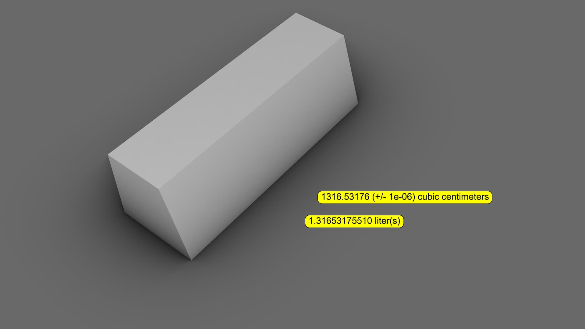
Lack of a native tool to calculate the mass of closed objects… Thankfully, I can use 3rd party plug-ins such as “SolidWeight” and “Peter’s tools”. SolidWeight.rvb (3.5 KB) PetersTools.rhp (136 KB)
Lack of dual tolerance option for “Split”, “Trim” and “Project curve”:
There must be an icon or a tick-box to quickly toggle the selection highlight. Extremely useful while working with dense 3d mesh models and point cloud data. The toggle must be visible all the time and the user must be able to switch it with a single mouse click, so the best locations is ether in the the Status bar at the bottom (next to “Filter”), or on the left side of the “Select all” icon, or on the right side of the “Properties” icon located below the Command line.
It will be even better to be able to apply the highlight toggle to a certain type of geometry, such like meshes only, while the rest ones will still take advantage of the default highlight.
There is no tool for Control point symmetry for NURBS surfaces!
We don’t have good tools for direct control point manipulation, as well…
The examples above are taken from some of my topics that could be found easily with the search engine. I can go on and on, but I think that you get the idea. Basically 95% of the important suggestions that me and other people here proposed over the years remain forgotten and will probably never see the light of the day. This is pity, because I LOVE RHINO and would like to see it become a far better and mature program than what’s it today.
please reconsider these statements, because important work to surfacing tools is being done as we speak. Note however that developing new tools takes time, and in case of surfacing tools, a lot of time. But I can assure you that input by you and others is taken seriously and is highly appreciated.
Hi @Gijs , as much as I want to be optimistic about the future of Rhino as a NURBS surfacing program, in fact I see really small progress across the recent Rhino iterations. Since Rhino 4 there are nearly zero improvements in the main NURBS modeling tools, especially “Blend surface” and “Match surface”, as well as “Rebuild”. If I remember correctly, “Match surface” in Rhino 4 was even downgraded compared to Rhino 3, by removing the “Refine match” option.
The examples in my last post clearly show lack of essential functionalities that otherwise could make Rhino a much, much better surfacing program.
I want to be able to convert surfaces to Degree 5 with 6 control points to work with clean geometry, but Rhino 7 destroys the intended shape of the surface and instead converts it into a chaotic mess of control points placed at extremely distant location, against any logic. @eobet also pointed out that huge bug in “Rebuild”, as did several other members here. Still not fixed, despite being one of the most important tools for NURBS surfacing directly related to the surface quality, file size and speed of work.
The “Interior shapes” option of “Blend surface” is producing highly inaccurate results. Take a look at this example.
Other inconvenience of “Interior shapes” is that it basically makes it impossible to adjust the major end handles in the way Rhino 5 allowed, because the preview blend surface gets loaded with extra dense handles that will not blend smoothly between the end handles. While the “Interior shapes” allow for a local adjustment in a specific small area of the blend surface, 99% of the time the users prefer to be able to adjust the general shape with the end handles only.
Turning off the “Interior shapes” option basically makes the Blend surface lose its ability to match to the input surface edges. Again, Rhino 5 had no problem with that.
I made plenty of proposals in the topic dedicated to “Blend surface” (I posted a link to it in my last post above), so I think that the Rhino developers already have more than enough ideas to work with.
The video I just posted here also shows another bug of “Blend surface”: unreliable preview that’s way too different compared to the output surface. Note that the control points of the blend surface are a total mess.
Another bug seen in this video is the automatic switching to the background program (Firefox in this case) while trying to place a floating panel inside Rhino’s viewport. It happens every time in my Rhino 8 WIP.
Also, lack of basic letters in some icons to distinguish them easily from the crowd of similarly looking icons. Now that Rhino 8 WIP removed the ability to draw custom icons inside the program, this becomes an even greater issue than before. For example, “Blend surface” could have a “B” inside the icon, “Match surface” could be marked with “M”, “Loft” may include “L”, and so on. The funny thing is that as some point of the same video I was confused where is “Blend surfaces” and spent several seconds into looking like a complete amateur who sees Rhino for the first time ever. Those few major icons must be really easy to spot.
Study the file yourself and see that it isn’t even close to being curvature continuous. Even if you try to match this surface, you will have a hard time without point editing or adding knots. blendsrf_rhino4.3dm (11.3 MB)
So my guess is that this sample file is not really representative to illustrate a flaw in BlendSrf
Note that if you uncheck Interior shapes and check the Refine option, you get the same result as in Rhino 4/5
The “Refine” option of “Blend surface” does not take into account the user-set file unit settings (distance 0,001 mm and angle 0,1 degrees in this case) and that alone makes it unusable most of the time, unlike the great flexibility of the “Refine match” option found in “Match surface”. If you run “Blend surface” with the “Refine” option and then run “Match surface” to match the resulting blend surface with the “Refine match” option set to the same 0,001 mm and 0,1 degrees, you will notice a huge difference in the way Rhino handles both of these refine options.
“Blend surface” should utilize the adjustable nature of the “Refine match” option of the “Match surface” tool, because it gives the user a freedom to inside the command. It would be even better to implement a “Rebuild” option inside “Blend surface” (basically the “Explicit control” option found in the major surfacing tools in Alias).
With regards to the removal of the “Refine match” option from “Match surface” in Rhino 4, I can’t download the evaluation version of Rhino 4 (it redirects me to Rhino 7), hence I can’t check if my memories are right.
As for the inability to draw icons inside Rhino 8 WIP, I failed to find any good tool for doing that, unlike the paint tools in Rhino 7. On theory there are some drawing tools, but they are unusable. Even in the latest Rhino 8 WIP they are way too buggy and produce weird results (at least on my Windows 10 at 4K with scaling 200%). Thickness of 2 works most of the time, as well as 4 in rare occasions. However, trying to draw something with thickness 1, 3 and 5 produces unexpected results. There is no simple eraser, too.
The icons there lack visual appearance to show that they are actually being pressed. It’s a guess game what’s going on there.
Objects such like lines, rectangle and ellipse lack any editing points to alter their shape subsequently, which means that the Undo button will be used tens of even hundreds of times to edit a single icon. You can take inspiration from Paint.NET to see how useful its objects drawing tools are.
imo that functionality belongs in the tool itself - there’s so much stuff like this where the proposed solution from McNeel is a very kludgey work around. The cumulative effect of all of these work arounds is that doing anything with the native Rhino tools is incredibly slow.
Are some of the core, long standing bugs/issues on MatchSrf being worked on? For instance the issues I show here:
To do high quality classic patch modeling, you really only need about 5 tools, but they need to be done right. A well behaved MatchSrf is one of those 5. As it stands right now, MatchSrf has some truly fundamental issues when matching above Tangent. Will there be improvements to these core issues in MatchSrf in V8?
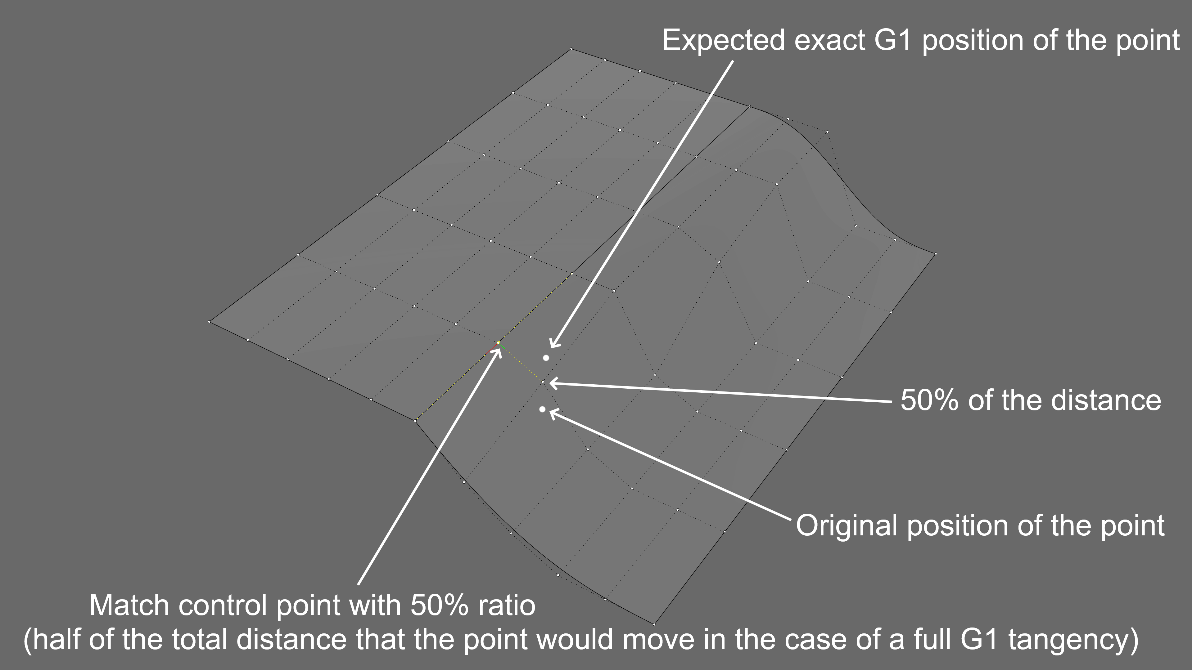
“Match surface” must have a “Preserve flow” option which will try to match to G2 without destroying the 3rd row of control points by moving them sideways in the same direction as the 2nd row. This should be done by adjusting the 3rd row of control points along the normal direction only. Obviously, the “Preserve flow” option while matching with G2 will produce a minor lack of true G2 curvature, lets say G1,9 , at the cost of preserving the general distribution (or flow) of the surface’s control points.
Here is a manual demonstration of how this could be achieved. The result is not a perfect G2, but is very usable, will not destroy the original placement of the control points (when looking at them from top view) and is far better than G1.
@Gijs There is a piece of low-hanging fruit I’d ask McNeel to include before the V8 feature freeze - RH-59057.
To have a history-enabled, native Rhino command that creates a single-span surface with edge and interior point control. Currently, _Loose gives you that ability, but only in one direction. This is really useful in a number of surface modeling use cases.
While we wait for V9, Loft Loose could give us a workaround for a lot of these issues if the U direction wasn’t locked to deg3.
There’s a workaround for converting single-span curves. There’s a workaround for having a custom symmetry plane for single-span curves. There’s a workaround for blending srfs with curves…but for surfaces, not one Rhino command will accept control crvs or a control poly and output a single-span srf.
matchsrf and blendsrf have problems to handle continuity and point positioning for curved surfaces in u and v directions (not developable)
as long as this topic is alive and the developer makes improvements to the matchsrf command, I would like them to see these two examples.
@Gijs@pascal
ex)1 ex1 matchsrf.3dm (148.9 KB)
there are two surfaces of degree 3
in fact it is only one surface that I divided in two with the split command
the continuity between the two surfaces is perfectly continuous.
but by applying the matchsrf command on one of the two surfaces
the distribution of the points corresponding to the curvature is destroyed and the continuity degrades a little, the points take the shape of a crossing in opposite direction, like an x .
what is intriguing in this example is that the isoparametric direction of the target surface in the U direction is not twisted.
normally the surface that undergoes the operation remains absolutely straight, especially for the two choices (auto )and (preserve diraction)
by using the command blendsrf to connect the two surfaces A and B
the command does not manage to position correctly the points corresponding to g2, g3 and g4,
however, this is a fairly easy connection condition (bezier surfaces of the same degree, no sharp oscillation, no bounded edge).
I find that blendsrf and matchsrf give the same result. I don’t know if they share the same code behind the scenes or not.
one thing is for sure, the position of the control points that correspond to G2, G3 and G4 is not correct,
the points should not be where they were positioned.
if I understood correctly, blend and match seem to make their own isoparametric projection on the target surfaces to achieve the desired contunuity.
the problem is that this projection does not always coincide with the real direction of the iso (especially in the case of non-developable surfaces).
in the file you find blue curves that I have drawn to show what the two commands refer to in this situation,
they are twisted and do not follow the isoparametric direction at all.
you also find the correct solution for all examples.
yes I’ve seen this before.
it belongs to the same kind of bug, just a little different.
yours shows that match doesn’t take into account the shape of the base surface. it always draws the g2 points straight along the g1 point vector. which destroys the base shape of the surface
while mine shows that match does not refer to the target surface at all.
I gave a straight u-shaped target surface, to get out of the way of this mess mentioned by you and bobi.
despite this, match can’t understand that it’s already straight.
this is specific to develepable surfaces.
both match and blend commands are infected by this problem. they tend to cross the g2 points in the opposite direction.
@sgreenawalt curious to know what vsr gives for these two examples ?


")