Hi there,
Currently I’m using Rhino 6 Evaluation and I managed to find several bug in the program that were not present in Rhino 5.
-
I have 3d Connexion SpacePilot (the old discontinued model, not the more recent “SpacePilot Pro” one) that works flawlessly in Rhino 5, but in Rhino 6 I noticed that 3d Connexion’s automatic rotation center no longer can “see” through solids and surfaces that were given a custom “wireframe” viewport setting through the “SetObjectDisplayMode” command. This bug is highly inconvenient, because the rotation center struggles to find the proper location on top of the visible geometry, and uses the invisible geometry of the nearby “wireframed” objects as a reference instead. I mainly use the “SetObjectDisplayMode” command to hide the geometry of objects while still having their wireframe visible in the scene. For me, this is a game changer in Rhino 5 and being unable to use it properly in Rhino 6 prevents me from buying the program at this moment.
-
Rhino 6 has issues with custom arrangement of toolbar menus. For example, every time I start Rhino 6 with various toolbars arranged at the bottom, the “Osnap” is missing, even though it was there in the last session. No matter how many times I save the toolbar settings, the “Osnap” toolbar is always missing and probably this error is caused by the presence of other toolbars at the bottom. Usually I place the Osnap toolbar at the bottom and then place several tabs with other toolbars on top of it. That was not an issue in Rhino 5 where everything worked as expected every time, so I consider it a bug in Rhino 6 where it is unable to do so.
Since it works in Rhino 5, I think that this bug in Rhino 6 is something that could be easily fixed by the team at McNeel. -
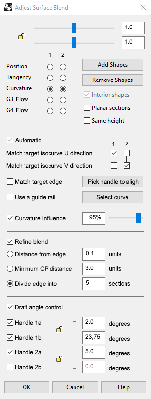
In my Rhino 6 Evaluation version (6.2.18065.11031, from 6.3.2018) the “BlendSrf” command sometimes performs worse than the same command in Rhino 5. Maybe this is caused by the introduction of the newly adopted “Interior shapes”. Example:
a) When I build two simple flat surfaces with Degree 1, then use the BlendSrf command between them, Rhino 6 will create a Blend surface with Degree 5 (CV count = 6) and Degree 1 (CV count = 2). Just like it did in Rhino 5.
b) But… If I rebuild one of these perfectly flat surfaces with Point count 10, Degree 3 and span counts 7 in both UV directions, the Blend surface that I already had (with History enabled) will rebuild itself into a surface with Degree 5 (CV count = 6) and Degree 3 (CV count = 4).
c) If I do the same with the second surface, then the Blend surface rebuilds itself into a surface with Degree 5 (CV count = 6) and Degree 3 (CV count = 10). This also happens if I delete the Blend surface and try to build a new one. Then it will automatically have 10 rows of control sections (shapes), which is very disturbing, because that will not allow me to have a more smooth control over the shape of the blend surface. In Rhino 5, I can add as much extra shapes (through the “Add shapes” button), but the default control shapes are always two (at the start and the end of the blend surface), allowing me to manually adjust the intermediate shape the way I wand. Since Rhino 6’s BlendSrf command will add a lot more control shapes by default, I no longer can have an easy and smooth control over the whole shape, forcing me to edit multiple shapes at variable rate.
If I only rebuild one of the original two surfaces used for the creation of the blend surface inbetween, the history is still enabled and any change in the control points of these two surfaces will affect the blend surface, too. However, if I rebuild the 2nd surface, the blend surface will no longer have its history enabled.
I also noticed another bug. If I use the BlendSrf command with the “Interior shapes” option off, sometimes the resulting blend surface will lack proper G2 continuity. This never happened in Rhino 5 where the continuity was perfect at all times. While using the “Interior shapes” option solves the problem, that comes at the cost of many extra control points that were not necessary in Rhino 5 to achieve virtually the same result.
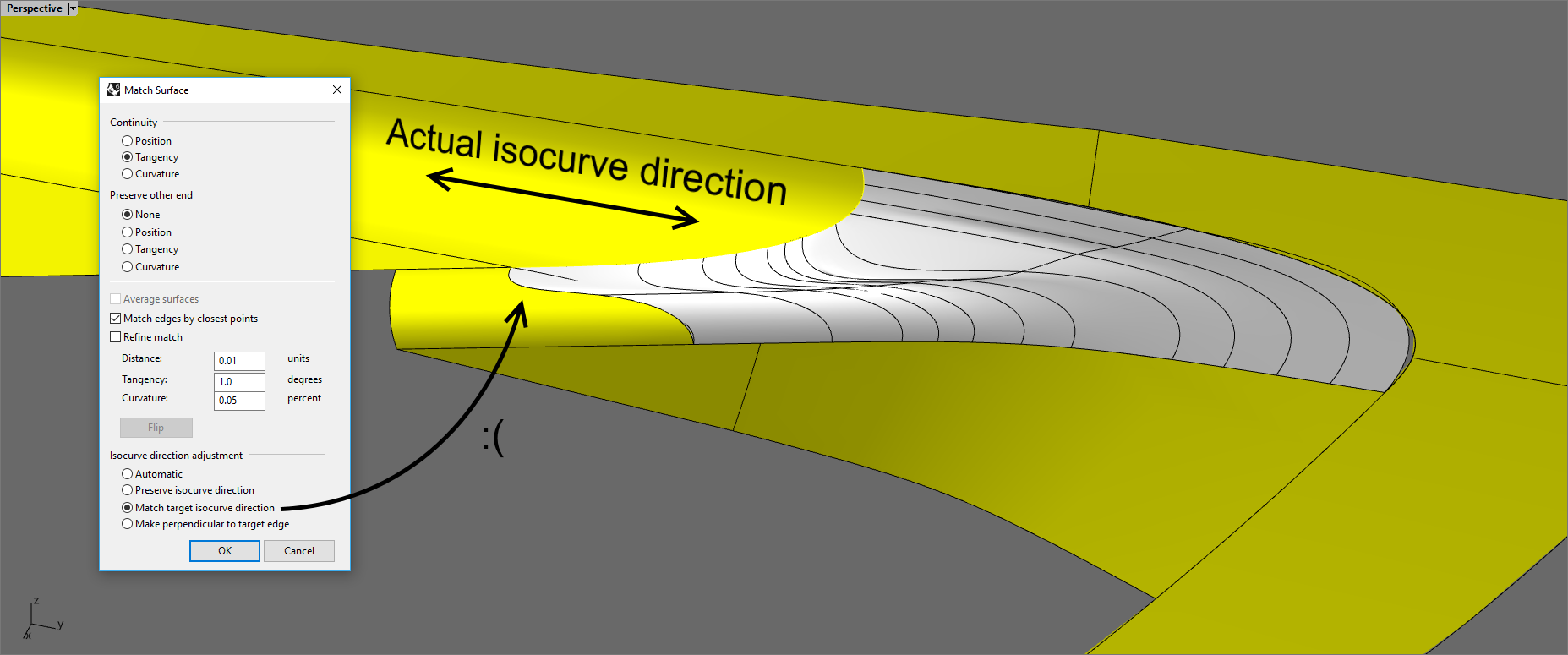
- There are bugs with History enabled for splines/curves, too. For example, if I match one end of a spline to a surface or solid edge, then I split that edge in another location (or if I extract a surface from the solid model), the spline’s orientation gets flipped automatically. If the history gets broken or “confused” in similar situations, is not it possible to just show a warning, or at least preserve the curve the way it was before the edge/surface/solid was affected with the Trim, Explode or ExtractSrf command?
===================================================
I also have a few suggestions for the BlendSrf command:
-
Is it possible to add a “Relax shape” option whose purpose is to smooth out the middle rows of the blend surface, without affecting the height of the surface at both both ends? The “Same high” option works in a different way, trying to equate the height of the surface.
-
An option “Use guide rail” would help a lot, if we were able to pick a spline that the BlendSfr command could use as a guide for its middle body. This is somewhat implemented in the Patch command and I find it quite useful. Sometimes I use splines together with the “Flow along curve” to affect the position of certain control points of surfaces, including blend surfaces, but that’s also slow and different than having the option by default in the menu window of the BlendSfr command. This will basically turn it onto a “Sweep 3 rail” command.

-
Make it possible to move sideways (along the rail edges of the blend surface) as much control points as the user wants, with “Relax” option separately along the U and V directions that affects only the selected control points. The UVN command is too limited and slow in these situations.
-
Ability to divide the blend surface (while still into its creation phase) into a number of sections, where the user is able to set a different, individual continuity setting to each section. For example, if I want to create a blend surface whose last 25% smoothly turn into a crease line, then the program should allow me to divide the blend surface into 4 sections where I set G2 for the first 2 sections (equal to 50% of the total length), G0 for the 4th section (equal to 25% of the total length) and the 3rd section (another 25%) is leaved for the smooth transition between G2 and G0. The resulting surface should have 50% G2 continuity, 25% transition from G2 into G0, and 25% G0.
In the same way, if we have the blend surface divided into 10 sections, we will be able to create advanced blend surfaces with greater control over the overall shape.
Some CAD programs feature similar custom input, but in a different way.They allow the user to set a custom length from the end of the blend surface where it will lose its G2 continuity in favour of G0.