Hello,
i am trying to have a correct print preview in layouts but cannot achieve it for both available plan and section options in visualarq.
When using vaPlanview (default style, no overrides) everything comes out both in print and viewport as black, even if hatches and/or other geometry have a print color assigned and no assigned print widths are considered, everything is in a single width.

Now lets say we need to to edit this to get the needed results. After exploding the view nothing is a polyline. I am trying to think of practical applications of having every outline curve of a wall, split in every neighboring element like walls, windows etc. I was expecting to have every outline of walls or columns in both section and projection as a discreet polylines, without any extra vertices in every apparent intersection with other elements. Does this make sense?
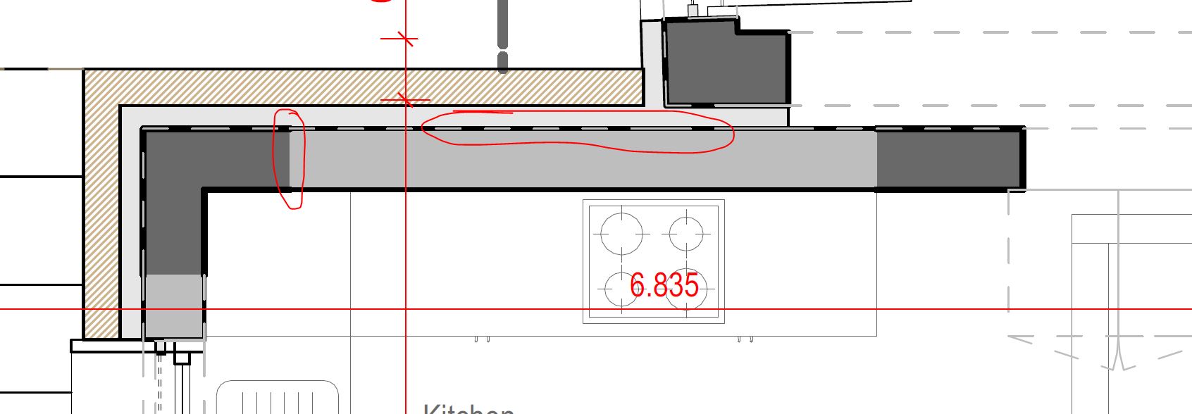
In the following image, the wall section has 4 segments, which when joined end up with 0-4 vertices, in places wherever the wall touches another element like a window etc., where i think it makes sense to have the blue version, ie 1 closed polyline with 0-1 etc vertices.

The above applies also for vadwgexport of layouts with plan views in hidden mode.
Coming back to print preview, when using plan view in hidden mode in layout print display does not work as expected. Projected geometry is displayed ok with both print color and width, but section parts have only correct print width but wrong color. How can someone make an accurate print display?
Now the above, while not diplayed correctly they plot ok to pdf vector, with the right color and width.

But, draw order is a mess and i cannot find a way to send to back or bring forward 3d walls, columns windows etc.
If there were to be default draw order rules, maybe the following could be valid for most cases:
hatches should always be in the back, then section curves should always be above projection curves and lastly for both, section and projection curves, thicker widths are always above thinner ones.

Then, is there a way to control hatch print width? Cannot find one, making any hatch pattern other than solid kinda useless, printing in default print width(?), but cannot find where to reduce or increase width.
Lastly, vectors have some weird artifacts. These results are with 600dpi resolution in print dialog.
These might be to small geometry

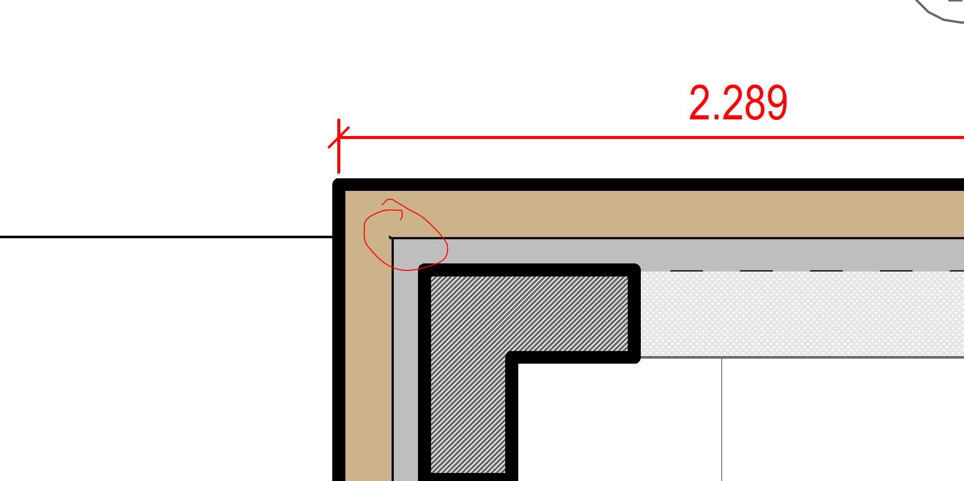
This is where two walls meet each other and touch with one column.

These are stool feet in projection.

Please let me know if i am missing something, how to improve if possible the above issues, or any workarounds to current limitations are welcome, be it visualarq or rhino tips.
best
alexandros.