hi all, I can not understand the meaning of the component “void” Rhino.inside.revit. Its output is brep, same as the input. Is there a way to make revit void ? (not the void family). Thanks!!!


hi all, I can not understand the meaning of the component “void” Rhino.inside.revit. Its output is brep, same as the input. Is there a way to make revit void ? (not the void family). Thanks!!!
Hi Vu, The Component Family Void is for creating Family Void Elements.
What are you trying to Cut?
For Walls and Floors you can use the Opening Components

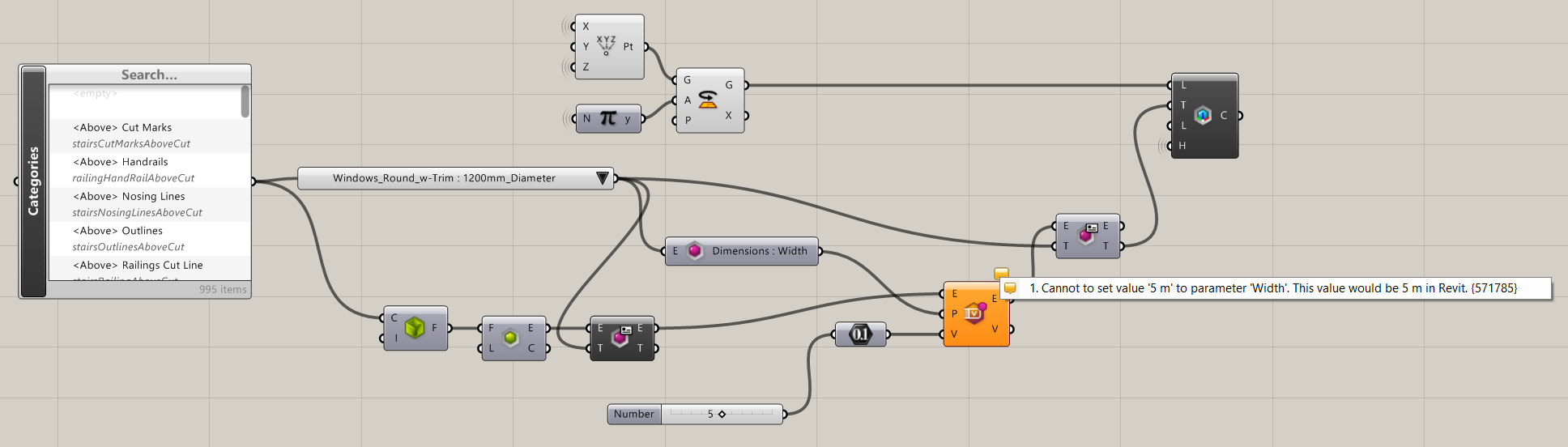
Here’s a nice example of using Voids in Families
Hi @Japhy is it possible to subtract a void to a wall? I was thinking to use the component family void because the opening is circular.

Yes, I think I could also insert a circular window… but i should modify also for example the radius of an existing family. Do you think it is the easiest way to do it?
Here’s an quick example of adding a ‘opening’ at piping locations in a wall and setting the diameter of the opening per each pipe diameter.
This could be done a lot better, just a rough example.
RE_window_as_Opening_Revit2022.1.rvt (1.7 MB)
RE_Window_As_Opening.gh (14.0 KB)
Hi @Japhy, if I want to proceed with a window opening, modifying the radius parameter, could it be this the correct way? Sorry to bother you, I m quite new to this plugin.
its a little off.
This is an instance parameter or type parameter?
If it’s a instance parameter you will want to change the Elements in the projects (here gathered by the a Family Filter)
If it’s a Type Parameter you will want to modify the type.
Hey @Japhy - I think I’ve asked you a similar question in the past, only now getting around to following up about it. I’m looking to do the same thing as above (create a void opening within a wall geometry) but it’s not rectilinear or circular. At the moment, I’m producing my geometry as a DirectShape “wall”, which creates the form I want but doesn’t otherwise act as a wall within Revit (for example, no detail linework when cut in plan, not taggable or editable, etc). See below for current status of elements:
What I would instead prefer to do is construct this as a series of line- and arc-based walls, and intersect each with the overall cutting volume as a void. This way, I could retain the ability to tag and modify within Revit. Sketched below are loosely where the arc divisions would occur in this same wall:
Do you have any thoughts on how this could be approached? Another question I’ve had is how to construct that portion of CW (which is curved in both plan and elevation). At the moment I’m populating the doors as a rectangular CW (curved in plan) and using direct shapes for the mullions and glazing, but it would similarly be ideal to have these as real Revit elements long-term. Something we can discuss at a later time!
Thank you,
Alex
Hi Alex, Can you send me the files again? Thanks.
If too big for email Upload
@Japhy Rather than sharing the actual file, here is a minimized sample which is looking to achieve the same thing. I’m referencing two Revit walls and creating a bi-arc between them (which I can populate into Revit as two individual arc-based wall elements). I have a Rhino curve (which is being extruded to intersect) that I want to use to create a void within these two wall segments. The ideal solution would be to build as wall elements so I can retain the linework as shown in plan (in this example, a thicker “finish” on one side of the wall, thinner “finish” on the other side). With a DirectShape, I can get the solid geometry I want, but not the visual appearance in a production drawing. See below for images, and attached for Rhino, GH, and Revit example files. Thanks!
Thanks, Try adding a Void to a new component generic model, then cut. It behaves nicely if its a Revit friendly curve.

@Japhy - I’ve set up my definition to match what you’re showing, but still not getting any results. At first, I thought it was due to your comment about Revit-friendly curves, but I reconstructed the curve as a simple arcs-and-lines closed curve and tried extruding, with similarly no result. I then inserted a simple rectangle, as you have demonstrated, but still no void within the wall geometry. My interpretation of your comment is that the category of the New Component Family should be a generic model, is this correct? Is it possible I need to manually perform the void/cut operation in Revit after the geometry is created? In my case, placing an Element Geometry component after the New Component Family yields no geometry (which might be expected anyways if it’s void geometry…). Thoughts?
You will need to manually Cut the void on each of the Walls, once cut the Family can be changed unless the curve gets too complex.
Okay, this is making sense now. The last issue I’m having is that the void element still isn’t showing up in the model. I can add the family manually from the project browser, but manual placement is unreliable. What might I be doing differently that’s populating your void directly into the model, while I have to place mine?
I just placed mine. Seeing as this is a one-off you can create your Void Geometry in Rhino and make your generic model at that location, then place your new family at 0,0,0.