Hi everyone,
I’m having troubles with this waffle that a friend helped me piece together. It has been working fine all this time, but when the waffle density is changed at the beginning of the definition, only certain instances (density: 0.5, 0.8) will have all waffles showing. Otherwise, one waffle in the U and V directions is always missing. Something about the waffle density stops those slats from intersecting, so the definition can’t establish an intersection between the two and so can’t cut slats. Any help with this/even a different method would be appreciated if it works!
GH file + images attached
Update: in the images for some reason all the contours in one of the directions aren’t showing up altogether!
Thanks!
Ryan
Just trying to make sure that there are no more contours than there should be, sometimes in this definition the List Length panel (in your screenshot) produces far more in one direction than the other even though they’re attached to the same waffle density slider. Thoughts?
I don’t see any evidence of that. Did I miss something?
I didn’t try to analyze (or change) your flatten/graph choices, though some may be unnecessary? I removed the culling that @lars.renklint mentioned, and some other unused bits. Did some minor consolidation of redundant components, removed the Clean Tree components as they appear to do nothing.
Your results look excellent to me, nice work! ![]()
Waffling_Troubles_2019Nov23a.gh (447.8 KB)
The extremely long delay (2+ minutes) to render the model bothered me so I dug back into it with the intention of cutting the slots BEFORE extruding the contour surfaces, thus avoiding the painfully long SDiff (two of them, ~1 minute each!).
I didn’t get that far yet, though still like the idea. In the process, I managed to break the model several times and can see how easily things can go wrong. I’ve put Humpty Dumpty back together again, still using SDiff but substantially faster than before. 
Among other things, I removed Wires, Join and Cap by extruding the lofted intersection surfaces. I used PShift and Flip Matrix to better manage grafting, which I believe is why SDiff is faster. The flattened ‘B’ inputs were causing more work than necessary.
I’ll leave it at that for now. Look carefully to compare the Profiler benchmark times.
Previous version: (Waffling_Troubles_2019Nov23a.gh)
New version: Waffling_Troubles_2019Nov23b.gh (446.6 KB)
Thank you @Joseph_Oster @lars.renklint you guys are awesome! It looks like it should work fine but for some reason the contours in the X direction are still fighting back. GH is unable to produce boundary surfaces from the X contours altogether and I can’t figure out why… our curves are the same internalized ones so I’m not sure what else could be causing the problem. any ideas? I’m running GH 2014 and Rhino 5, but the components are all still the same 
Here’s a simple demo of that idea:
RegionDiff_2019Nov24a.gh (6.5 KB)
And here it is applied to waffling. WAY FASTER than SDiff!!!
Waffling_Troubles_2019Nov24a.gh (454.3 KB) (DEPRECATED due to error, see version Waffling_Troubles_2019Nov24c.gh below)
@ralscham, I’m not seeing that problem. Does this model work for you? But the part you are referring to hasn’t changed at all. Are the joined curves feeding Boundary not closed?
Hahah that’s pretty cool! I’ll see if I can apply that to this once this whole waffling thing has blown over.
This model isn’t working for me either, it appears all the curves are closed but Boundary still returns no results… the screenshot is with both boundary components turned on
That’s weird and sad… I can think of various things to check and try as alternatives but since it works for me, I don’t know if it would fix your troubles.
Are all the joined curves closed and planar?
Instead of contours, you could try plane intersections instead? Can you do that?
ISN’T IT?? They’re all closed. Not sure if they’re planar though, I attached the Planar component but not sure if I know how to read it. Some of them are vertical and some are horizontal. I also played with the document tolerance to see if that might make a difference.
Now get this, I tried a different waffle density that I know usually works (0.5) and it sort of works, but only two of the waffles in the X direction show up rather than none. Does that mean anything to you? @Joseph_Oster
I also went back to my original definition from the waffle that I originally posted (with my desired waffle density but that generally doesn’t work), and now it works? It’s still posting the error messages on some of the components, but it’s creating a waffle… Ever seen anything like that?
You’ve got the mystery GH blues, brah. So sorry for you.
What about applying contours to a surface instead of the mesh? Oh, I see the problem with that; your current mesh effectively has two surfaces, top and bottom… ![]()
And by the way, I’m not going back to SDiff, it’s way too slow with no advantage.
P.S. For whatever it’s worth, here is an adaptation of the model from the other thread that gets the top and bottom surfaces separately. As you can see, the edges cause GIGO artifacts.
surface_from_points_Ryan_2019Nov24a.gh (922.5 KB)
Is it possible to get the top and bottom meshes separately? You could convert them to surfaces before adding the vertical edge surface that connects them, to create a “Closed Brep”. Perhaps then get cleaner results from Contour?
Yo baby, we have achieved solid “Closed Brep” from the mesh! It waffles fine for me, how about you?
Waffling_Troubles_2019Nov24b.gh (110.8 KB) (DEPRECATED due to error, see version ‘24c’ below)
Here’s how I did it:
surface_from_points_Ryan_2019Nov24b.gh (443.7 KB)
P.S. I noticed a very small but significant error. The slots don’t align perfectly due to using a domain (-x/2 To x/2) that centers the rectangles on the intersections. Easily fixed.
ERROR: (Top View)

CORRECTION:

Waffling_Troubles_2019Nov24c.gh (121.1 KB)
Hahaha how did you possible find that this was the problem?? That’s crazy! Thank you it works, you’re a legend!
I’m not surprised that the “Closed Brep” contoured better than the mesh. The tricky part was converting a two-faced mesh into two NURBS surfaces. Would be easier if you did that as a separate step before connecting them to create the “Closed Brep” solid.
The small misalignment of the slots was an error I introduced myself so I knew immediately where to find and how to fix it, once I noticed the slight error.
AH this is awkward, because I do actually have two separate meshes already! The top and bottom surfaces were created separately, then turned into a mesh to use Kangaroo, and then joined  I’m sorry I hope that didn’t overcomplicate things
Yes, joining the two meshes certainly did make it more complicated for me to convert them into NURBS surfaces, requiring some forensic analysis to extract the two base surfaces. If this is going to be a regular work flow, I suggest again that you convert the mesh results from Kangaroo to NURBS surfaces before making the two-sided “solid” that you are waffling.
A “Closed Brep” is a beautiful thing. ![]()
P.S. To put this another way @ralscham, the code from the other thread that converts one mesh to a NURBS surface was quite simple:
Below is the code (surface_from_points_Ryan_2019Nov24b.gh) I posted in this thread two days ago, adapted from that simple model. The white group converts the bottom of your joined mesh to a NURBS surface, the cyan group converts the top surface of your joined mesh to a NURBS surface, and the yellow group is all the extra stuff I had to write to extract the top and bottom from the joined mesh and then loft a vertical perimeter surface to join the two NURBS surfaces into a “Closed Brep”.
Most of the yellow group wouldn’t be necessary if the two meshes from Kangaroo were handled separately, before they were joined together into a mesh that doesn’t contour well.
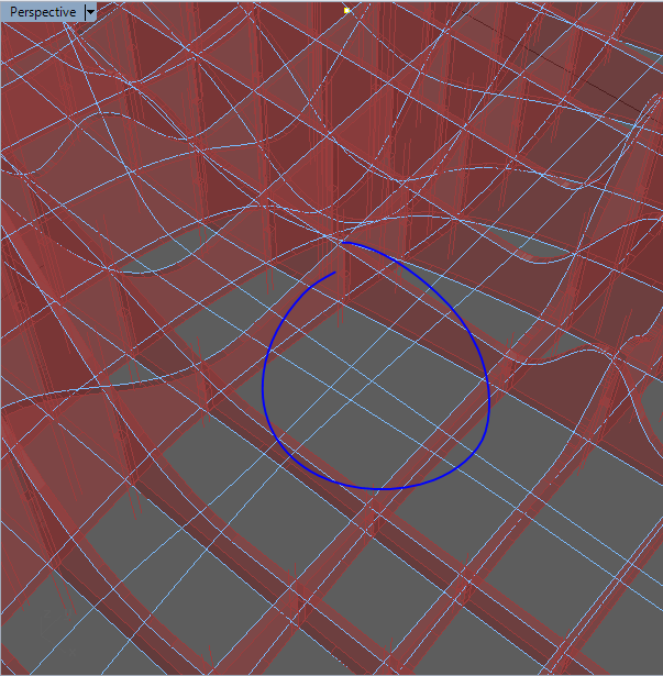
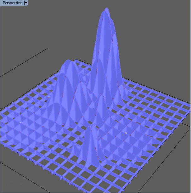
Hi guys, unfortunately I’m having to revisit this topic. I finished this project thanks to your help, but when I returned to it to make some changes, this waffling portion of the definition stopped working AGAIN. I was wondering if you could help me understand why it’s doing what it is. Contours in one direction are not creating boundary surfaces altogether, I’m not sure why that is. Also, the edge contours in the opposite direction are not even being recognized by the boundary component, but boundary surfaces are being created between them in the opposite direction. I haven’t changed anything since you last helped so I’m not sure why this is happening ![]() I thought perhaps changing the form of the object would help, but it hasn’t. I’ve attached some pictures and the portion of the defintion. Would greatly appreciate any help on this
I thought perhaps changing the form of the object would help, but it hasn’t. I’ve attached some pictures and the portion of the defintion. Would greatly appreciate any help on this ![]() thanks again! @Joseph_Oster @lars.renklint
thanks again! @Joseph_Oster @lars.renklint
200120_Waffling Help.gh (2.0 MB)


