I see that in the file that you attached. When I delete the clipping plane, all geometry in the clipping drawings should also be deleted but here there are a few curves that are remaining.
Do you know which steps it takes to get into this situation?
Trying to open that file instantly crashes Rhino on my end. I’ll try opening that on a different machine…
-wim
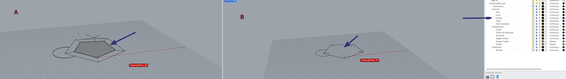
Geometries are IsolateToViewport A, because of that “Surface” portion of section is only visible in A and not in B. I think Surfaces should be visible in both view ports, similar to produced lines.
IsolateToViewport will make all geometry that is selected for that command only be visible in the viewport that is selected. In all other viewports (including details), that geometry will not exist. That is the entire point of that command.
I’m not sure if you are reporting that you are selecting a curve and a plane during that command, and that, when the command is done, the curve is still visible in all viewports? If so, I’ll need steps to reproduce that issue.
-wim
I got what IsolateToViewport does, but now I think I also understand why produced by ClippingDrawing command Surfaces and Hatches are not visible in other viewport, but Curves produced from edges are… it’s because in ClippingDrawing AddBackground=Yes.
So, even if objects are not visible in given Viewport (and thus are not sectioned) they are still visible as a Background. I must rethink that, but at the first glance it’s strange that something invisible will still be visible as a Background.
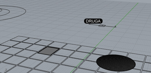
Also, AddBackground seems to be the reason for the Curve “retention” when I modify the ClippingPlane position. Take a look.
They are on the MODEL::320 Layer (which is hidden).
I think it does (at least for now) - at the current state of things, there are so many ways to cut the mustard that it can be somewhat confusing, but I like the direction. Stacking drawings might result in some very sophisticated 2D representations that are non-destructive, which is great.