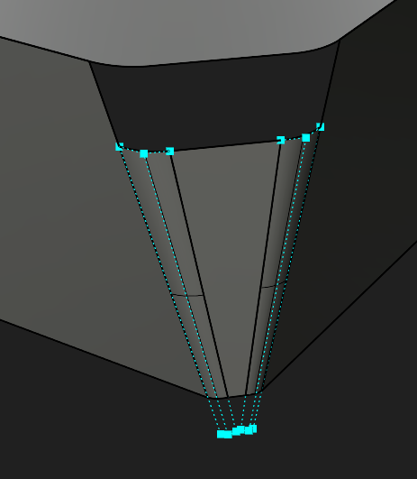
I’m brand new to Rhino, but have experience with other CAD software like SolidWorks and I’m having a hard time figuring out how to achieve comparable results. In this particular example, I want to be able to add a surface to fill in this open area and have it tangent to the 3 sides. In SW, I could use a boundary surface. In Rhino, I would expect to be able to use the “surface from 2, 3, or 4 edge curves” command or the “surface from network of curves” command, yet neither seems to work. Patch works, but does not give the desired result.
Related question - is there a way to select multiple tangent surface edges as if they were a single curve, like edges 1, 2, and 3 below?
I’m sure there are some basics I’m just not understanding, so any help will be appreciated. Thanks!
There’s ways to do that but I’d like to step back and ask why you’re trying to do this like that? For making things in Rhino to go nicely and give nice results you have to look at things beyond “here’s a hole I have to fill in.” I wouldn’t even be worrying about those little blend/fillet surfaces right now, I would be trying to smoothly trim off your base box with one nice surface, then rounding off the edges.
This particular geometry is just some arbitrary thing I started making to try and figure out how to use Rhino. In general though, I can see this situation coming up and would like to know how to handle it.
@G113 The edges you’ve labeled as 1,2,3 – are pointlessly disconnected. A big question is how that deterministically occurred.
If we were setting up dominoes, and I removed a few of them when you weren’t looking, then took a photo and said “hey how do I fill in those dominoes” – would that make sense?
You’ve missed the point. I want to know how you could connect tangent surface edges to actually use them as if they were a single edge/surface. Yes, my above shape was not realistic, but the general scenario is not an uncommon situation when surfacing.
cooking up an abstract example which might be handled fully different in reality is not very much on point either in fact that is much rather missing the point itself.
if you share a real situation then i am sure you will be learning far more sufficient.
Hello- ExtendSrf past the top plane on all three, then trim with the top plane works but the trimmed radii on the top plane are not correct for extensions of these surfaces, so I’d replace that plane with a PlanarSrf from all the surrounding edges. I think if the input surfaces were tangent, it might be cleaner to close up, but they are not.
I’ve got experience with Solidworks so I think I’m qualified to advise that the approach you’re hoping to use won’t translate over into Rhino very well.
However, I’ll show you why: in this first example, I’ll close the hole by adding new surfaces. Instead of patch, I’ll use Sweep2.
As you can see, the continuity isn’t great with this method.
However, in looking at the underlying surfaces, they’re unnecessarily complex for what this geometry basically is: a box with a chamfer and some fillets on the chamfer.
A bit of NURBS surface theory, surfaces have degrees. The more points there are, the more “math” that surface has that you can use to define its shape. You can increase the point count by adding knots/spans, or upping the degree.
So in your example, the middle surface (I assume) is supposed to be flat, so it can actually just be a degree 1 surface in both U and V directions.
They don’t need to be trimmed surfaces, so I also ran RefitTrim on the bottom edges, this is necessary because the fillet surfaces aren’t matched to their neighbouring surfaces well:
The continuity plug-in I’m using is Global Edge Continuity.
Instead of closing the hole with another surface, it would be easier to extend each surface and then trim the top of the box back to wherever they intersect.
In the video above, I:
Manually re-build the flat middle surface with DupEdge and deleting the unnecessary points
RefitTrim the lower edges of the fillet surfaces
MatchSrf the fillet surfaces to their neighbouring edges, making sure to check Tangency under Preserve other end
ExtendSrf all the surfaces past the top surface of the box
Discover that the edge of the box is not aligned properly, so I use Split by Isocurve with Shrink=Yes and split it where the edges meet
Trim the top surface and the top edges back so they all meet
Now that I’ve written this all out, I’ve realized this is a lot of steps. Depending on whether you want a quick and dirty result or one that is clean and easy to work with down the line, the two methods each have their pros and cons.
It sounds like the answer to the question: Can I select surface edges from two tangent surfaces as if they were one is “no” when it comes to the 2,3,4-sided surface and surface from network of curves commands. (Although it does let you chain edges for things like blend surface). Is that correct?
Here is a real-world example of a part I made (not sharing due to proprietary reasons). Disclaimer, I’m positive there are better ways to have built this, BUT I ended up with this situation. Basically two primary surfaces, A and B, “share” one face, and I needed a custom transition/fillet to nicely join the corner region of the intersection. The software I was using let me do that with a single boundary surface, but it sounds like in Rhino I would need to tackle this a little differently. Is that right?
As I understand it, to me, it sounds like you’re interpreting the situation from the perspective of the typical parametric-3D-solid-modeling world, and not the 3D-freeform-surface-modeling world.
Technically there’s two things happening here, one is merely a struggle of nomenclature differentiation, but second, mainly the struggle is the misunderstanding that there is ‘no spoon’.
See, Rhino is a surgical tool, one like no other. With Rhino you’ll eventually realize that you will gain perspective in anything you ever thought you saw in any of your CAD files from any other CAD’s.
It’s not about whether you can ‘select edges from two tangent surfaces as if they were one’. It’s instead, realizing that they never were ‘one’ and will never be ‘one’ unless you really really kinda want to make them ‘one’.
But have to ask your self, are you sure they need to be ‘one’?
See, other CAD’s will lie to you and make you think things are one thing, when in fact they are many compilations of entities – not just one.
You see, solid models aren’t really solid, and they aren’t just a blob that gets added to or subtracted from. Well, unless you’re playing with voxels or meshes, but even then, they’re comprised of many countless constituents, not just ‘one’.
However, yes you can “chain edges” or extract and join or rebuild, change degrees, etc.
I’m not sure what “a single boundary surface” means, but yes Rhino is less of a smuggy approach and more of a surgical specifc approach.
So, from that image it looks like at least 7 adjacent surfaces that would comprise a boundary that would contain at least 7 or more constituent curves/lines/polycrvs/polylines etc… depending how you want to look at it.
You could build that “surface in question” in Rhino, (at least) 4 different ways. It all depends on design intent and desired outcome.
It looks like you have the edges identified though:
You are correct, I am coming from a parametric 3D mechanical CAD package world. I can still make freeform shapes with Solidworks, but yes, the method is certainly a bit different.
A “single boundary surface” was meant to refer to those other CAD packages’ version of a surfacing tool that can take 4 outer input curves/surface edges (and optional interior curves) and make a surface. Basically what appears to be (at least somewhat) comparable to Rhino’s “NetworkSrf” command.
I have no doubt there are ways to build this in Rhino. My question was whether I could use that same strategy from something like Solidworks and apply it here - e.g. could I use a single NetworkSrf command to bridge between those 7 edges. They are 7 edges, but really I look at it as if they are only 4 true edges since there are several that are tangentially connected. Right now I do not know how to do this in Rhino.
I did not fully understand what you were suggesting about making new G1 surfaces - can you explain in more detail or point me to the relevant command(s)? It sounds like you are suggesting that you would somehow first make a single surface out of those tangentially connected edges and then use that as one of the inputs for the NetworkSrf command?
There’s at least 4 ways to do it. How many ways can solidworks do it?
Not necessarily, but yeah that’s probably at least one of the four or more ways it could be done.
The question you should be asking is, are there 7 or are there 4, and does the design intend there to be any, and how many…and what degree(1-11), and what point composition…etc. Does the curvature need to be G0,1,2,3,4, or does it matter…
You know, the things that solidworks and programs like it, don’t show you – or they smudge it and ‘move it under the carpet’ as a wise man has said.
I’m not looking to argue/compare how many ways this can be done in Rhino vs. SolidWorks. I only brought SW up because that is the modeling background I currently understand, so I want to know if there is a (more or less) 1:1 equivalent method in Rhino. Either this specific modeling method is not possible in Rhino, or I need help understanding the required steps. To clarify, in this example the goal is for the surface to be tangent (G1) to all of the surfaces it contacts.
I’m also interested to know more specific details about some of the other methods, but my main question is the above one about if/how to solve this using a SW comparable approach.
I think you’re missing my point. There’s not really any argument. Connotations are infinite, so whatever you choose is up to you.
It’s more like an opportunity for comparison if any.
But until someone provides some evidence well this meme seems pretty accurate:
jk!
Mostly what I’m trying to get you to understand is 1:1 has nothing to do with it. It’s not whether you can bend the spoon in one program with one command and bend the spoon in another the same way with the other program.
It’s about one program like SW makes you think it’s a spoon that is being bent, while the other Rhino shows you the actual constituents the spoon is comprised of and the fact it’s not a spoon at all in the first place.
Rhino is a surgical tool that reveals things to the user that the user would never even know were there in the first place with those silly other programs like SW.
Unless of course something changed in the last ten yrs in SW, but I doubt it. It’s probably the same old watered down version of CATIA.
Indeed. There’s certainly possibilities of getting there, but it seems like you’re waiting for something. Another life maybe.
That’s good to know. One less degree of freedom to worry about.
Comparing apples and oranges, while wanting to know what one can do without demonstrating the abilities of the other.