Hey,
I’m looking for a solution to this problem that is driving me crazy. How can I make panels once I have made a circle packing on a mesh previously generated with kangaroo?
All this to generate the bearing structure of a shell (then to be passed in karamba).
Initially I had simply mapped the catenary mesh with a voronoi grid generated on the flat mesh, then relaxed to obtain a more regular geometry with polygons (more or less hexagons and pentagons, etc)
I simply thought of intersecting all the planes generated by the circle packing but this I cannot do because they also intersect each other several times.
I could use the intersection of the spheres generated by the circles, but this would require the enlargement of all the circles to allow the intersection, certainly a lot of calculation time, and in any case it is not said that all the spheres intersect.
Ironically I would need something similar, but inverse and on a 3d mesh, to the process of what is described in this discussion … Maximum inscribed circle - Grasshopper
Thanks a lot to those who can help me!
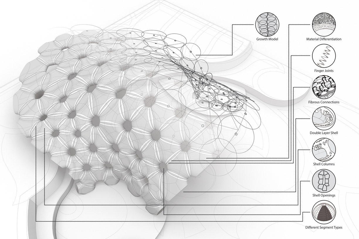
P.S. I don’t know how they made these panels but I really need something like this (it is not strictly necessary that the faces are planar) Landesgartenschau Exhibition Hall on Vimeo
Ok folks, it works well.
Unfortunately it is very very slow, 12 seconds per 345 pannelli.
In the end I used the “Plan e Region” (in the mathematical intersect tab).
I listed each circle and entered all the plans together in the “Bounds” field. maybe this is what slows down the processing (I don’t know how the heck the professors of the Stuttgart ICD did! maybe one or more more powerful CPU / s. Or maybe there is a deception?)
Perhaps it would be ideal for a quick and interactive visualization to be able to insert only the circles adjacent to the circle to be paneled.
If anyone comes up with something to speed up the process, he is welcome!
Never mind, obviously this cannot work on my mesh.
The problem is due to the fact that the plane is infinite and being a double curvature surface with recesses, it also intersects the planes on the other side …
I wonder if there is a way to reduce the size of the plane (physically not only visually).
I keep wondering here too: how did they do for the Stuttgart pavilion? since there is also a double curvature there and the planes would intersect.
If I remember correctly ICD used an agent based system for the panelling, not just plain circle packing. Nevertheless what you see as panels is the mesh dual of the delaunay mesh of the circle center points.
The theory behind why that approach is used is that if 3 edges meet in one vertex the mesh is easily offesettable whithout planning cutouts.
The only problem with your mesh atm (atleast the one that was referenced in the 2nd file) are the holes, so either delete these faces from the delauny mesh or use a different technique to get to the delauny mesh.
Hi Daniel,
Yes, I had already seen that the optimization of the panels in the ICD pavilions takes place through agents, but what interests me is the process by which they manage to make the panels.
Really interesting this approach, I had already tried to create a mesh by delaunay triangulation based on the origin of the circles, to then take advantage of its duality.
This, however, as you rightly foresee, creates problems in cutting the mesh, so the entire triangulation process is almost useless, since small and altered triangles are generated at the base.
edit.
I found this repository on the github of the computational design team the design of the ICD / ITKE Research Pavilion 2015-16, but I don’t know how to use the .cs files inside the grasshopper to try them.
I have very few skills with Visual Studio, now I see what I can do. Thanks for your help!
The delaunay method applied on the circle packing of my mesh shelldoes not seem to give the desired result, at the base the faces are too distorted and there are too many irregular polygons. Besides, I would still need to manually create the missing segments at the base later.
That’s right, but I didn’t mentioned it since it’s not the full build just one component, check the size.
Check your messages in the forum, I did send you the compiled. gha
It’s not clear to me what kind of shape you want to tesselate since its switching with every post. It looks like the one form the gif has to much curverature in certain areas. And the starting mesh seems not good either.
Thanks guys, I’m glad to get so much help. I hope this is an interesting topic for the forum!
I see how this .gha that Daniel compiled works, I hope to succeed in the task in order to load the .gh file for those who need it in the future.
My biggest thanks to GeneKao, for the wonderful work he shared. (there is not here but he’s present on the old forum Gene Kao's Page - Grasshopper)
For completeness I add this article that I found today which describes the approach of making panels using adjacent planes and the variation of the position of the points on mesh.
Hi @Petras_Vestartas
Thank you for your help. Do you mean like the following image?
When I create a new project, I do it this way, but when the project is ready, I do not know how to do it. Can you please tell me what to do?
The adjacent panel intersection is not so difficult, since you can get this from a mesh topology or closest point search or delaunay triangution. This is the component in ngon plugin, called planar faces. The problem is how you get those center of the cells…
Thank you very much, I did the following steps: “Solution Explorer…”, “Add References…”, “Browse…”, and select .DLL files. Previous errors were fixed but I still could not build the code and it failed.I attached the list of errors as a pdf file.