Model View Detail WIndow Issues

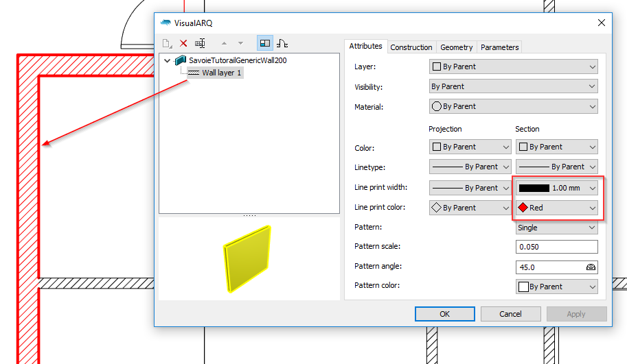
1a) The only way I can select this wall in this Model Plan View Detail/Viewport (Villa Savoie Tutorial North West Corner First Floor) is where the arrow is located in the attached. At a window jamb. Most can be selected at their perimeter, but not this one.

.
1b) As I adjust line display to be “By Layer” and assign a thick line print width to the layer, this wall type displays with a thick outline around the window openings but not at the cut plane like all the other walls, which have the same settings and are on the same layer.
1c) In the case of the wall which is displaying with outlines at the cutplane (Left - Ground - Plan), the thick outlines continue at the window sill also. This is of course undesired but I can’t tell how to have outlines only where the cutplane intersects the wall (and thus not at the window sills.)

  1. The wall joints are visible (note the 45 degree lines at the 90 degree corners in these pdf prints) and come and go (regardless of setttings, as far as I can tell) in the Rhino layout view (with “PrintDisplay” or not).SavoieTutorialFromTemplateCurrent 005preAnomlyTest1.pdf (216.9 KB)

  2. The door swings, as visible in this print, are sometimes present and sometimes not - this seems to change without any change of setttings. This inconsistency is present in layout display in Rhino, too. But the swings are always there in the Top-Ground Model Window.SavoieTutorialFromTemplateCurrent 005preAnomlyTest2.pdf (106.6 KB)

  3. The thresholds show in all the prints but not in any Rhino displays.
    Would like to control this.

  4. I am throughout the above attempting to create plans with a dark grey fill and thick black outlines where a cutplane cuts through a wall. Removing hidden lines is an issue in a few places using Wireframe Mode, as well as the other issues above. I have tried HIdden Mode but it will not display a difference in colour between edge line and fill. If, in Options>VIewModes>Hidden, Edge>Width is set to “1” (the lowest value) and Edge>Colour to black, this setting fills the wall cavity with black, obscuring any colour set for the fill.
    Hidden mode doesn’t seem to assign line weights based on Layer colours; maybe wall styles will work.
    Please advise on how to accomplish this. I’ll send the file I’m working with.

1a) I cannot reproduce this issue. I can select that wall at any point but from a former file you sent me that I think is not the same as the one in your screenshot.
1b) If you assign the line print width (as section attribute) of that wall layer “by layer”, it will take the line print width assigned to that layer, which will be the same as the print widht assigned to the edges of objects in that layer shown in projection. I should take a look at your file, but I’d dare to say you have a thicker print width assigned to the layer “Walls”, and a thinner print width assigned to that wall style layer in projection. But send me the model so I can take a better look.
1c) This is either a bug, or something that is not set properly in the attributes settings. If you share the file I’ll be able to figure it out.
2. I cannot reproduce this error. I would need the 3dm file. I assume you are running VisualARQ 2.2, is that right?
3. I cannot reproduce this error either.
4. I cannot reproduce this error either.
5. Using the Hidden display mode, you should be able to control the color of sectioned contours. You can assign that section color from the Attributes tab, for VisualARQ object style components, or from the Section Attributes icon in the Properties panel for Rhino geometry:


It’s very strange that I could not reproduce most of the issues reported here, so I look forward to getting your model so we can figure out what’s happening. (Send it to visualarq@asuni.com).
Thanks,

1a)Yes, it’s a different file. I’ve sent permission to the dropbox file (it’s too big to upload or email) now to the email address you suggested.
1b/c) I can get most of this to work (except for the one anomalous wall), but it uses the same thickness for the window sills in plan. I’ve been supposing that Wireframe Mode doesn’t distinguish between Cutplane line widths and other line widths so the problem could be that I should be using a Hidden Mode, but if Wireframe Mode should be, then something’s wrong.
2-4) I hope the model will demonstrate those issues.
5) Not having much luck with Hidden Mode at all today with this project, First I couldn’t select objects in Hidden Line mode, and the display went buggy:


The Detail WIndow on the right is copied from the one on the left. I updated my display driver, but the problems remain. The best display I can get when working in an active Detail Window in Hidden Mode is shown below:
Sometimes it won’t select walls at all - here it will only select a particular round column, but nothing else.
This is all happening with the file that is on drop box, and an incremental save and new detail window isn’t better.
I have set the wall style to display as you recommended - Line Print Width (2mm for clarity here) and Line Print COlour (black) as desired, but all the wall edges in the Hidden Mode window display as default w Print Display. Both window print with 2mm thickness, but there are new problems with these prints in addtion to the issues above.
6) Print problems now that thicknesses are set in Wall Styles:
a) turquoise hairline between perimeter line and fill (despite being printed w B&W setting) Ed: Resolved - This is a CutePdf issue. Has to be chosen in CutePdf Properties.
b) corners of the perimeter line are radiussed rather than mitred
c) the thick perimeter lines in Hidden Mode view (on the right) aren’t present on all walls (as they are on the Wireframe Mode on the left)
d) No frames on the Wireframe Mode on the left.
e) Neither Mode drops the thick perimeter line away to show the Window sill
f) All wall joints are shown in the Wireframe mode, and some in the Hidden Line mode.SavoieTutorialFromTemplateCurrent 005preAnomly2 001-1.pdf (423.5 KB)

I can work around the above problems by not using an outline with different fill combination (for now) to depict my walls - just making them a solid colour. But the absence of door swings in these plans is something I haven’t found a work-around to, and I’d like it if that could be resolved first.

The issues further above may or may not be a formidable set of problems to resolve, and they’re important for my use and it’d be great to soon have a resolution to those as well.

Door Swings: They come and go - here are two identical Model View Detail Windows in Hidden View Mode: one displays no door swings, one displays them. The Detail Windows show the same objects and are identical (as far as I can tell) in Layers, Detail Properties, General Properties, Level Properties, and Section Attributes :


Here’s the project:Door Swing Issue .3dm (20.0 MB)

Rhino 6.5.18155.1361, 06/04/2018
VisualArq 2.2.012431 2018/06/13
I am running an i7-7700HG @2.8GHz, 16GB, WIndows 10 version 1803 build 171345.112
Display card is Nvidia GeForce GTX 1050Ti, latest driver.

I’ve discovered what causes the door swings to disappear. It’s resizing the Detail Window:

That’s an undo and redo of a reduction in size of the window causing the swings to disappear.

1a: Got your file, thanks!
1b-1c: The Wireframe display mode should show also the difference of lineweighs, but remember to enable the Print Preview. However, depending on the wireframe lineweight settings, it may be hard to appreciate the difference of thicknesses. With the Hidden display mode you will appreciate it better, and it is actually the display mode you should use to print the model to vector output. In any case, checking out your model, I can see you you have assigned the same lineweight to that wall style in section and in projection. So you should change that from the wall styles dialog. I’ve set a printwidht of 2.00mm so you can appreciate in Wireframe mode the difference:


2. I opened your model and the joints are clean and looking good. Either in the plan views (that still show the former hatch pattern “single” assigned to them, as the model view (where walls have a “Solid” hatch pattern.). But of course, if you see the model in Wireframe mode, you will see those wall join lines.

3 I could reproduce this one. I don’t see the doors swing from page layouts either. Good you found out it happens when resizing the Detail. We will take a look at this.
4. I still cannot reproduce this issue. I don’t see the tresholds under the openings. Is this happening with the Hidden display mode?
5. I could reproduce these issues too with Hidden display mode in page layouts. I think it has something to do with this particular file, but we will try to fix it as soon as possible. Since there are issues with the display of the model, the lineweights and other attributes are not showing correctly.
6a: which setting in the CutePdf do you edit to do not show that hairline between the perimeter line and fill?.
6b: Can you point me out where this happens?
6c I see, we will take a look at that.
6d Do you have a screenshot of this?
6e I cannot reproduce this one. Sill thicknes seems to show properly. Is this happening in the final pdf? in Layout view? or in Model view? image

6f I don’t see any wall shown in wireframe mode in that pdf, but I do see some printing issues, that we will revise.
Cheers,

1a) Wall unselectable at Perimeter. THis should be an issue on the model I sent.
1b-c) Wall Displays thick at Sills - actually the file I sent I’m pretty sure that the line print width was set to By Parent for both Projection and Section. But the print width for the object is set By Layer, and the Layer print width is set to 2mm. So I think that’s effectively the same thing.
2) Joints Visible. Actually it doesn’t seem to always show in wireframe view, though I understand why it should, and hidden is the mode I need here anyway.
3) HIdden Door Swings I’m going to have to set my Detail View sizes and leave them, or maybe recreate them if I have to change them. This is a very difficult one.
4) Door Thresholds Showing This one hasn’t shown up for awhile. It might have been from the cutplane being turned off, though when I do that the display gets corrupted on the model I sent. It was only in Wireframe.
5) Black Outlines, Grey Fill for Walls at Cutplane
6a) Turquoise line in prints The Cutepdf Writer has a properties button. It brings up a print settings which offers B&W, which has to be chosen or that line shows as turquoise even if RHinos print setting is B&W
6b) MItered corners at perimeter line If you zoom into the corner of any wall in this pdf (same as the one I uploaded previously @ 6f above), you can see that the corner perimeter line makes the corners of the wall look rounded (you have to zoom in to see it on a monitor, but it’ll be quite obvious in a plot. Makes the walls look like cartoons) instead of square.SavoieTutorialFromTemplateCurrent 005preAnomly2 001-1.pdf (423.5 KB)
6c) Inconsistent Perimeter line Plot of Cut PLanes in HIdden Mode You have got it.
6d) (to clarify) Door frames not showing in Wireframe plots Visible in the plot above.
6e) Thick lines at sills. Visible in the pdf. Sills are thick. Wall Style setting may improve this.
6f) Wall JOints Visible This is natural, i understand, to Wireframe view, but not to Hidden, and seems to be connected to 6c.

I’m getting around as much as possible of these issues by dispensing with a visible outline other than default, and using a solid black fill, for walls.

But the issue with dimensions (other post) and door swings are formidable.

1a) Wall unselectable at Perimeter. - I can’t reproduce this error.
1b-c) Wall Displays thick at Sills - Yes, the file you sent me has the print width of the wall set to “By Parent” for both Projection and Section. But if you do so, and then you assign the print width of the wall object By Layer, and the Layer thickness set to 2mm, then all edges of the wall, (in section and in projection) will be 2mm thick, including those at the sill. In order to avoid this, from the wall styles dialog, assign a different print width in Section than in Projection.

2) Joints Visible . In Wireframe mode the joints will always be visible, but in Hidden they should not. If you have any model where joints are visible in Hidden display (the one you sent me looks fine), please let me know it.
3) HIdden Door Swings I’ll let you know when we fix this one.
4) Door Thresholds Showing Ok.
5) Black Outlines, Grey Fill for Walls at Cutplane Ok
6a) Turquoise line in prints Ok
6b) MItered corners at perimeter line I see what you mean now. I don’t see those round corners though when I do printing tests with your file, but we will investigate it.
6c) Inconsistent Perimeter line Plot of Cut PLanes in HIdden Mode Yes, got that.
6d) (to clarify) Door frames not showing in Wireframe plots I think some door frames were “swallowed” by the thick wall line and for that reason you didn’t see them.
6e) Thick lines at sills. Yes, I as mentioned, setting a different thickness to the wall in section and in projection will fix this.
6f) Wall JOints Visible Ok.

Thx
1a) It’s the least of them, but you have the wall in one of the downloaded projects. It’s the exterior wall on the middle floor level, running N-S (assuming N is up) at the NW corner. If you put a standard window in it it should exhibit the issue.
1b-c) I hope to figure out settings heirarchies.
2) Wireframe is the only Mode that reproduces the necessary lines with issues. Hidden isn’t workable.
6b) The issue is how they print. (I’ve learned not to expect wysiwig with CAD.)

1a) I don’t know why you cannot select that wall and how to help you on this. I can do it with no problems with your model.

@djhg, we have fixed a bug that was causing difficulties when selecting objects in Details with the Hidden display mode. This bug is fixed in the 2.2.2 version that is already available for download: VisualARQ 2 - Version 2.2.2 released

This has been fixed in VisualARQ 2.3