I’ve spent hours watching various tutorial videos on mapping UV’s, but have yet to figure out how to get my mapping to flow along a bent pipe scenario so that the displacement changes direction like a texture would.
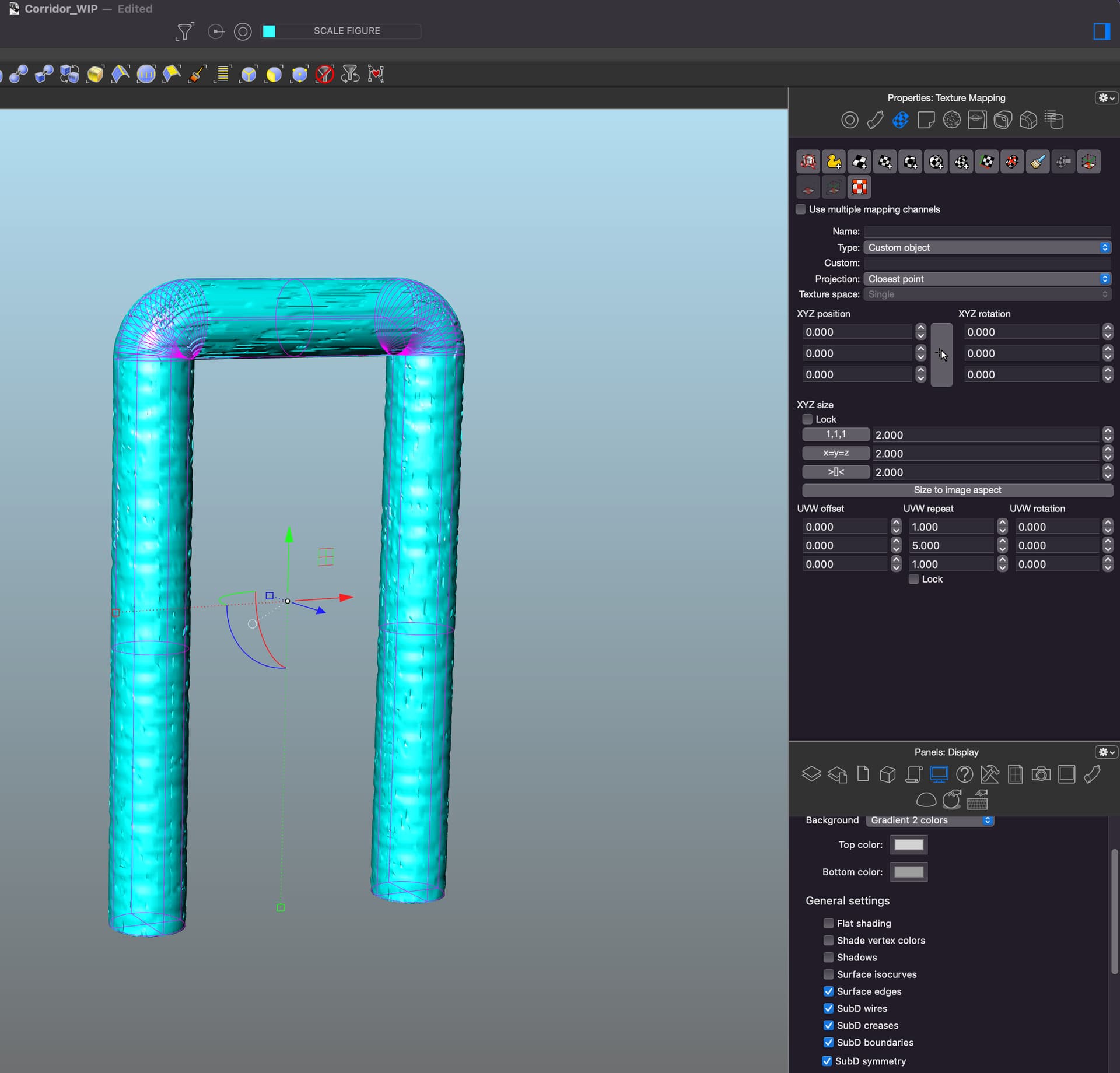
As you can see from the screen shot, the displacement works great on the vertical cylinders, but once they turn at the top, the displacement does not change direction. I’ve tried using Unwrap to select seams, I’ve also tried using multi-channel and doing a custom mapping based on the extracted surface of the top cylinder along with a box mapping - but I just can’t seem to get this to wrap around the object correctly. Any suggestions would be greatly appreciated.
Interesting as I had used the pipe command, so I figured that would have been similar to a sweep. I used the sweep 1 w/ refit per your suggestion, and the texture map is certainly better, but I’m still running into the issue with the displacement. Using the same displacement applied with the same settings has a totally different look, but still does not “wrap” properly. Perhaps it has something to do with displacements in particular?
Hi @kevinhoulihan, take a closer look at my example and the settings used in the assigned Material / Color Texture / Mapping section. Your problem is likely related to the values you changed here:
You cannot get a seamless mapping on the pipe using Box mapping. Once you’ve created the pipe as described above it uses surface mapping by default. There is no need to change any of the values in the Texture Mapping panel.
Instead control the repeat values in the material for the color texture under the Mapping section. To find the proper values, i’ve measured the pipe curve’s length and the length of one of the pipe’s circles. This should give you a relation for the u and v repeat values.
@kevinhoulihan If you post the polysrf I will take a look if you still need help. From the images I would split the surfaces to create a continuous seam if one doesn’t already exist and then Join it all back together before a custom Unwrap using the newly introduced seam. The alternate method as mentioned is to construct the form as a single surface and leverage default surface mapping.