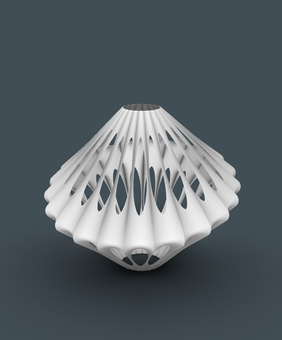
HEllo i am new to grashopper and i wanted to recreat a shape to make it like a Christmas tree. in the photo its a helix but used circle to have different section now i wanted to create the bars between the circles using lines that connect the different points on the circle. I dont know how to create the blade shape that is in the photo
any help is appreciated thanks.
It is pretty complex, if i say so myself. I made nurbs and mesh versions, without too much thought into it. In case I’d want to recreate geometry precisely, I would need to spend a lot of time doing this.
that is an interesting approach thanks for sharing. I havent been able to install weaverbird since this morning though. I tried solutions online but nothing seems to work do you know what could be the problem. it shows this message
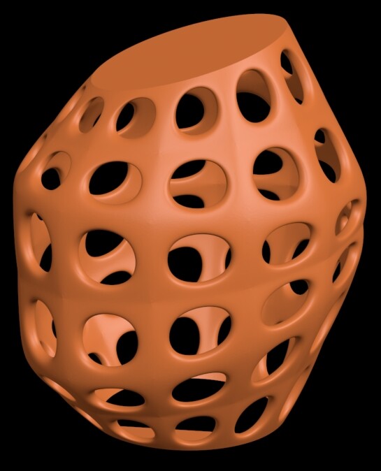
I found your WB solution to be quite fascinating since I am fairly unfamiliar with meshes. (They seem like some sort of black magic to me.) So I took the liberty of tweaking your script to make it amenable for 3D printing. Frankly I really didn’t know exactly what I was doing, but this is the first almost printable result I came up with:
The major problem is with the top and bottom “naked edges” your script produces. 3D printing slicer programs don’t like naked edges, so I fixed them with the Netfabb utility, and that produced the geometry for the shape in the screenshot above. What’s shown could probably be printed, but it really isn’t correct and would not look very nice when finished. But it’s pretty close to being printable.
What I can’t figure out is how to deal with the top and bottom naked edges your script creates. They look like this:
That’s a rather scary image for me since I’m used to dealing with closed curves & Breps, and I don’t know enough about meshes to make much sense out of these curves. So I was hoping you might be able to point me in the right direction to ending up with something like a closed Brep. Thanks for any insight you can provide.
Never mind - I found that by decreasing the size of the holes the mesh the wbNaked routine returned 4 nice curves from which I could make boundary surfaces that solve my problems. (I have no idea why this happens, but it’s the end result that counts.) Thanks again for sharing your solution.
I don’t think this is true. You can see from the screenshot that @hadjisarra0 posted, she’s getting the Unrecognized Objects dialog when she tries to open a grasshopper definition that uses the Weaverbird plugin.
@hadjisarra0, try running the _PackageManager command from Rhino and installing Weaverbird from there.
I am not proficient with meshes either… I think for any professional my definition is kinda cringe. What I would like to know though, is how you solved this problem, using boundary surfaces? BoS it is nurbs, and trying to convert it into mesh, would give vertices mismatch, like here - Join the vertices of two different meshes? - #12 by johnharding
I dont know how to solve such problems yet.
actually, I made another version, besides mesh edit and wb you need kangaroo for this one too. But only for combine&clean node magic, I am not using solver.
wow i have a lot to study after your conversation haha i finally managed to install weaverbird after installing rhino 7 and using package manager as you recommeneded thanks a lot. I will check your code carefully now. thanks for sharing. @dfytz1 and @Birk_Binnard thanks also for sharing your works and the tips. very interesting
The answer is: I haven’t got the slightest idea how I solved it. I ended up putting the guts of your script into a cluster and adding some stuff to connect/close the top and bottom naked edges. My “solution” is attached below.
I wanted to use a more interesting shape than a circle as the basis for this design, but I quickly found out I could not make that work either. Here’s a typical example of what happens with a 4-sided polygon:
It gets worse with more sides. I think one of the reasons for this is how Rhino “stretches” a surface around a set of control curves. Basically, I think the stretching isn’t evenly done for a Brep made with control curves that have different curvature values in different places. I could not find a way to make pretty holes with any kind of control curve other than a circle.
The good news is your method seems to work fine for circular control curves. In the past I’ve used 2 Loft surfaces as you do, but with holes cut into them with circular arrays of solid cutters. Then I went to great lengths (with a lot of help from people here) to fillet all the edges so I had a nice, smooth end result with no sharp corners. Your meshing method eliminates all of this, and the results are just fine. Unfortunately for me I don’t really know why (or how) your method works - so it’s somewhat like magic at this point.
You see, mesh join doesn’t work like brep join. It leaves all the vertices misaligned. You can even join meshes that do not collide with each other. You can think of mesh join as about group component… mesh join just places all the mesh vertices and faces to the same group. If you want to cap the bottom, the easiest way would be using mesh union instead, but consider that the output mesh would look awful.
Thanks for the info about MJoin - I didn’t know there was such a thing. Here’s what I found out about the 2:
Exporting the same geometry with Join & Union as an STL file produced the same results: 500,024 triangles with 8 errors. It’s fairly common for Rhino’s STL files to have errors - sometimes quite a few of them. Fortunately my slicer program has a direct link to the Netfabb software, and that is very effective with correcting errors. In this cane it ended up with 668,204 triangles and (of course) zero errors. I’m printing it now - results sometime tomorrow.
I am not sure about the order of these nodes, we definitely need someone who knows something about meshes
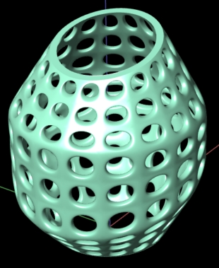
Also I made an attempt of capping the bottom, it has an OK mesh, but i do not think it fits the design perfectly meshcontainer_dfytz(with bottom cap).gh (46.1 KB)
do you mind sharing which program are you using ? Ill have to print the geometry as well. Processing: perspecitve 3.jpg… here is the code i received from @dfytz1 after modifying it a bit
If you mean which slicer program I use, it is SuperSlicer, which is an enhanced version of PrusaSlicer. For reasons unknown to me there are 2 versions of SUperSLicer posted online. I use the 2nd one - Arachne version. Here’s the link: SuperSlicer
Wow - I am much happier with the ability to use polygons instead of circles. So thanks for your work that enables this.
I did make several tweaks to your file. Changing the base was the major one: for designs like this one I don’t like the base protruding below the main geometry. So I replaced your components with ones that use a simple extrusion of the bottom polygon. This works fine for something with the thickness of the final mesh, and it also eliminated a lot of GH components you had to make a separate base.
I also simplified the sliders for the U/V values, and then rearranged everything in the cluster to make it a bit more readable.
I’ve always preferred shapes like this to be based on polygons with a prime number of sides. So this one has 7 which I think is a pretty good balance. One interesting thing (yet another one I don’t understand) is why adding any kind of fillet to the polygon, regardless of the number of side, blows the whole thing sky high. 3 sides results in a shape that just looks too sharp for me, so that’s another reason I opted for 7.
Note that the STL file that Rhino exported for this model had 627 errors in 844,236 triangles, but NetFabb fixed them all in about a minute. The fixed STL has zero errors and 844,236 triangles, which is unusual because the # triangles is usually larger. (More mesh stuff I don’t understand!)