is there a way in Rhino to create a proper technical drawing from a 3d model that avoids using the “Make2D” command (in the way Solidwork does)?
Hi 177 -
Yes. Create a layout and put details with the required views on that layout.
-wim


@wim
That’s actually a really good simple example.
Care to share the file for educational purposes?
Hi Toni -
Sure
→ drw from 3d model.3dm (2.5 MB)
-wim
it’s nice but not exactly what I meant when I showed SW dwg. You did the section (cut) in the model space and SW works with a solid intact 3D model.
And I even don’t talk about the lines style etc. because it’s important in tech dwg.
Thx for the model btw
Hi 177 -
Have you done any work in Rhino?
The 3D model is intact. The clipping plane is something that you can turn on or off per viewport / detail. If you absolutely want to, you can use the TestDetailSection command to create a clipping plane and detail in one go on the layout:
-wim
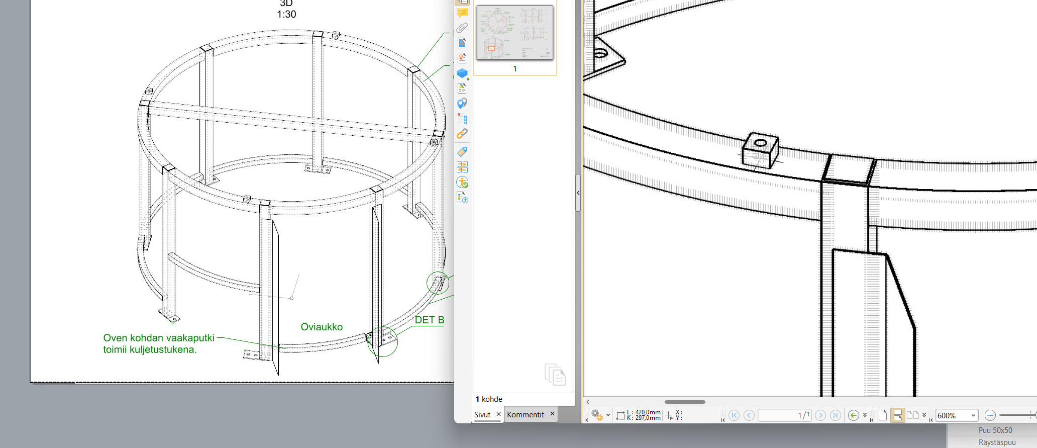
Totally doable. With solid bodies intact, and in one place in model space.
I don’t have any sections on this sheet, but even exploded assembly diagrams are possible if you tweak your workflow a little.

Rhino 8 on the left, finished PDF on the right. All vector, all lineweights adjustable (as are section styles, where you have them).
Check out some of the resources posted here. Super useful stuff.
So were you actually looking for help or trolling? It seemed a bit off. You know the rapidly dwindling population that gives a crap about technical drawings don’t consider SolidWorks any kind of pinnacle of the (again dwindling) art either.
Ooooh, that’s pretty neat!
didn’t check your model attentively, my bad.
it looks like it is doable, resolved.
@wim
I’m playing around with the Hidden linetype and its correlation to printed PDF.
-
As far as I can tell, the only way to print a non-black Hidden linetype in Technical viewmode is through printing “Display Color”. Is this correct?
-
The Hidden linetype settings control the printed result, but does not affect the display. Got that.
-
There seems to be some overlayed curves or something happening here, rendering the hidden line weird.


And as a sidenote - if the PDF print from Technical is this good in quality, how come you do not yet have a native Layout → DWG save/print?
@fsalla VisualARQ is working on it, but their implementation of it is unfortunately very different.
Fantastic drawing! Any chance you could elaborate on your workflow? How exactly are you going about exploding the parts?
Hi Toni -
For the time being, that’s correct, yes.
Yea…
I guess, in real life, those two parts would not have an identical diameter (unless you work with double minus tolerances on your drawings), and those two circles will be slightly offset?

But, yes…
As anything else, it’s work that needs to fit into the prioritizing schedule. It’s on the Rhino 9 list of things to consider.
Hi Simon -
Scott isn’t exploding the parts. Each detail only shows a single part of the entire assembly.
-wim
Oh, right. I should have looked at it more carefully. Thanks for the clarification!
@wim @fsalla @enric
There seems to be a printing bug here still…
VisualARQ beams do not print in vector mode in Technical.

Raster works, but Hidden linetype is screwed.
…just when I was getting excited about the possibilities in avoiding Make2D alltogether…
EDIT:
Interestingly enough, it works if I disable Tibidabo as Beams become just blocks.

So VisualARQ is overriding the Print settings on VARQ objects.
Rh8 SR16, VARQ3.2.0
EDIT2:
If I use BlockTools’ _MakeUnique, it strips the VARQ-layer from the block and everything works as expected. This is a workaround for my immediate printing needs.
Hi @Toni_Osterlund this used to work before (check this post: Hidden Display Mode that can show hidden beam web and flanges as lines - #5 by fsalla ). We will revise this issue again.
@wim already beat me to it, but yep. I create an isometric detail view of the whole assembly, then copy that at 30-degree angles, and use HideInDetail or layer controls to show or hide what I do or don’t want to see. Then I add the “explosion lines” manually.
I haven’t found a faster/smoother way to do it yet, but this gets me the results I need for now. ![]()
Edit to add: as for the actual parts, you can mostly thank McMaster-Carr for that one, heh.