I’ve been experimenting with making ship structural 2D drawings based on a 3D Rhino model. The model itself is molded line surfaces only, for both plates and attached shapes. My goal is NOT to define anything twice, which means not having a 3D model plus a separate 2D interpretation. The main problem is that far-side edges of stiffeners attachments to plate show as solid edges in “Technical” view, because the plate is a surface not a solid. Ideally, an object on the far side of something should be dashed, even where they have a common intersection. The idea here is not to create a solid construction model, but a simpler surface model with drawings suitable for functional/regulatory design. Has anyone solved this issue?
That’s because “technical” view is a “pretty picture” not a drawing.
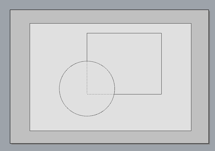
You may want to consider using layouts.
- You can set up multiple views per part
- Suppress layers and objects on a per-layout basis
- Modifying geometry modifies layout views
- Use technical view to properly render hidden lines
- Print to PDF, vector or raster image formats
Example:
This layout shows a sphere sitting atop a box. The box surface has been exploded (it is not a solid). Fig. 1: Top view; Fig. 2: Isometric view.

It’s not as clean and automated as the drawing system in fully parametric systems.
- No automatic way to create datum planes for dynamic sectioning
- Layout creation takes more work than, say, Inventor or Solid works. You can macro a lot of it.