Hi,
V5
The front wheels of this tractor are angled (real one not attached here as file size HUGE). I want to keep the top view as such, also front as front, right as the side view. as shown.
What are the steps to achieve this so I can work on the front wheel (nearside) and have it with a cplane acoss its side face to make creating tyre and rim etc easy ?
basically the tractor leans towards its offside a bit.
I made a cplane for halfway up the rear wheel with X axis and Y axis just higher up at wheel centre and origin as before just higher up at wheel centre and top view was then facing right to left ( still top of tractor), front view was now its right hand side and right view now its front. yes I know the views are not supposed to be front is front etc, but when I first create the tractor they are.
I also do like always to work with front is front, and can always do so unless I try for a custom cplane.
If someone can do a little step by step on a cplane make for wheel face I would appreciate it massively. origin in wheel centre by the way.
In the perspective view, use Set Cplane to Object and click on the wheel face. That should set the CPlane origin to the centre of the face so tyres, rings of bolts etc should be easy. When you are done, set the CPlane to World Top to put it back to its default setting.
If you are likely to come back to do more work on the wheel, you should save the wheel CPlane as a Named CPlane so it is easy to call it up again.
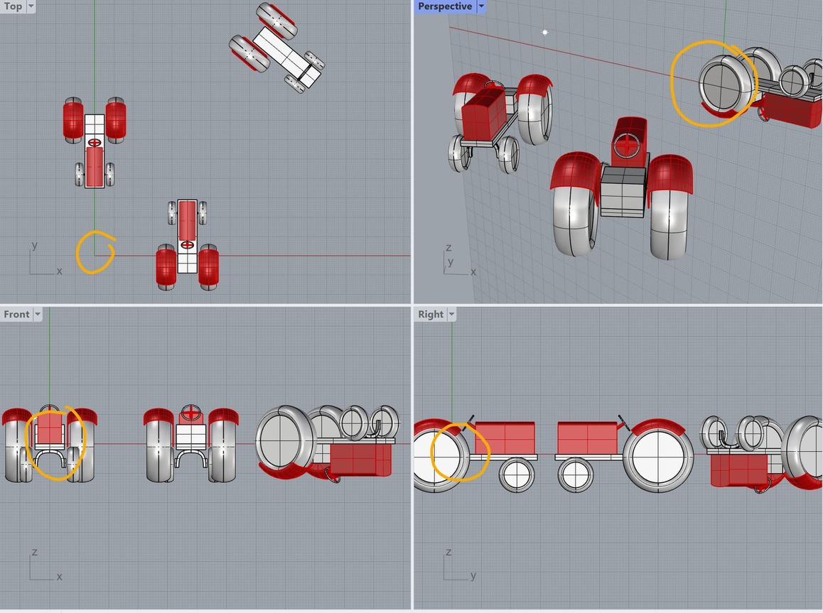
the lower screen grab is the comfortable logical views I had for top front and side.
I needed top to be as such with just a bit of tractor offside side showing, front would see a slight tilt to left.
Right would show a tad of the underside.
Hi,
V5.
I started with the same default views and new file Rhino has always given me, I dont know how to alter that anyway. I dont start with a template, I just go File New and chose this time small and inches.
Drew a rough tractor over the model and mesh I have in my serious workspace, exported it out and opened that, it brought with it the default cplane.
I did save that default cplane beforehand in views named cplane as Cplane 01 default.
I then went to perspective view and chose Cplane by object and in perspective view clicked the face of the wheel, and we see what I ended up with.
your example has a variety of views all in one view, not as per my tractor. you set cplane to object click the wheel face and nothing at all happens.
I could film it but have obj and suspect the file aize would be huge. Can we post a screen capture, perhaps snagit might work. How do we post such, just attach the video with the upload option ?
I had a convenient scene with 3 tractors in it (one overturned) and used that rather than waste time drawing a new tractor. And note that that was in Rhino 7 - but R5 does the same thing (although R5 tractors aren’t as pretty).
Well, apart from setting the CPlane to the wheel. But that was my point: it does not change the views.
All my illustrations are captured using Snagit, including the videos. You can upload them just like any other file (for videos, use Snagit’s Save As to make MP4’s).
Remember too that setting the CPlane only applies here to the active (perspective) viewport. In the other viewports the CPlanes are unchanged. See how the origins show this:
My file is as basic and out of the rhino box as it comes.
so why does my workflow of new file,draw tractor, to suit the view names (as my brain likes that, and no doubt others do) then in the icons tools at top choose cplane to object , click sloping wheel face and see all the views change ?
try your method on my nearside front wheel face, and video it, see what happens.
Then take 1 tractor and create a rhino new file, does it start with my views, top persp, right and front counting clockwise ?
Place the tractor as per mine, front of tractor in ‘front’ etc. make a wheel slope and apply Cplane by object to it.
I am using the tool icon Set CPlane to Object.
If it doesnt do what mine does then I need to find out why, because…
I have been plagued with this problem since day 1 of V4 !
as a result I am frightened to use cplanes.
if the origin doesnt move that is useful as well as needing to move it. If I wanted to move it do I use a different command to just move origin, that would do it.
NOTICE in my example origin did move, I never asked it to. what is going on ?
I like your lighting scheme, is that SHADED mode tweaked or as it comes in v7 ?
If I drill a hole in a block , and look at it (down the hole) in ortho view, you cant see it.
The origin that changes is the origin of the new CPlane (all CPlanes have an origin). That CPlane only applies to the one view.
Here is Crude Tractor video: The CPlane changes in the Perspective view and I go on to draw a circle on that CPlane (i.e. on the wheel face). As you can see, no views changed during any of this action.
If changing a CPlane is changing your views then you either have some more obscure setting to do that or you have a script or plugin making it happen.
Hi,
V5
thanks Kev R, that was the thing causing a difference,.
Just what is Universal v Standard, certainly not pleasant !
Jeremy, I followed Kev R advice, it was on universal, set it to standard. then see story board.
it did as your video, however what you then didn’t notice, as you didn’t ‘tumble’ the perspective view, is that the origin jumped to the wheel ! we see it happen in the video ! BUT its still where it was in ortho’s. NOW THATS UNUSABLE as one cannot have two origins !
apart from the moving origin only in perspective, thats what I wanted.
You say this method origin doesnt move, well TRUE AND FALSE.
Thats not good.
is this a bug ?
Whats it like in V7 ?
I then think how do I move origin back to where its in orthos, should I place a point at origin before doing the cplane to object command, then resite origin to that point ?
If Cplane no longer runs through that point surely thats not going to help as origin must be on cplanes which have moved, but it can as they havent moved, yet they have… my brain hurts !
Standard Cplanes: This is the default. The Cplane in each viewport is independent of the Cplanes in other viewports. When a Cplane is changed in one viewport the Cplanes in the other viewports do not change.
Universal Cplanes: This is an option. The Cplanes in the standard orthogonal viewports are linked and are orthogonal to each other. The Perspective viewport uses the same Cplane as the Top viewport. When a Cplane in one viewport is changed the Cplanes in the other viewports change to remain orthogonal with the same origin locations.
Each Viewport (“a monitor (2d)”) is is connected to a view, a picture generated by a camera, showing what is going on in this virtual 3d world.
Now if you want to input points, if you click on a 2d image, the trace of your eye is endless - hitting a cplane will define a precise position.
i think a very simple example example is a house, with a corner at 0-0-0 in World coordinates.
Now if you construct / position solarpanels on the roof, you will need a custom cplane.
check out:
_namedViews (to store views)
_namedCplanes (to store cplanes)
_plan (to get a orthogonal view on a cplane)
_4View _4View (twice - at least at the mac version) to reset standard 4 viewports and cplanes.
Well, remember setting a CPlane to the wheel face was done to make drawing on the wheel easy. What better to do that than setting the CPlane origin to the centre of the face? I could then draw a circle around the wheel by placing the centre at 0 (i.e. 0,0,0), the origin of the CPlane.
You can have lots of origins, not just two (or as you suggest, one). Every CPlane has an origin and they can all be different.
There are two types of origin: World Origin and CPlane origin. The only origin that is unique (and immutable) is the World Origin. All the geometry you create will be stored with respect to that origin. The CPlanes - construction planes - are just aids to make it easier to actually create that geometry, and it makes sense to place their origins where they are most helpful. AFAIK geometry doesn’t have any memory of the CPlane used to create itself.
My 2 cents…
Skip trying to use the scan to model on top of.
Bring the scan into rhino and do print screens of your views.
Scale the images in the appropriate viewports/cplanes to a few basic measurements you take off the scan.
Leave the scan in rhino to check your modeling against but turn it off to model and use the images.
Keep things basic and try to find plans that have dimensions or using the scan take measures and decide for yourself.
Notate and dimension your concepts. Keep notes in the notes area of rhino this way you have a log of your thoughts and measures.
The reason I say this is that using custom cplanes at angles is going to run into trouble downstream. All sorts of operations are going to fail or become really time consuming and difficult. The originals are done from ortho plans and then massaged in each machine shop that makes that part.
In the scan everything is going to be different to some degree and your working against yourself. At some point even the bolts will be different sizes slightly when in concept they are a standard size, and nothing will be ortho really; it will all be slightly off.
Notice in the Gaudi Sagrada scan post they created a conceptual model and a scanned model. Both have their uses. If you are modeling for small scale models you might have to conceptualize at some point.
Unless a photo is of a flat surface and either taken exactly normal to the surface or corrected for tilt there will be distortion due to depth.
When modeling boats from scans I use the scanned model and set Cplanes and views as needed.
Depending on the object not all ortho plans of components are aligned to the world axis system. For instance 2WD tractor front wheels typically have built in camber with the top of the wheel tilted out. The wheels, spindle, etc are designed using a tilted coordinate system and drawing of the spindle, etc would have been drawn using that tilted system. The same situation exists for steering columns, etc.
Why? One of the features of Rhino is the ability to use custom Cplanes which are not parallel to the world coordinate system.
Hi @davidcockey
That’s just my take on it that’s why I said my 2 cents. Of course you’re welcome to make things as painful as you need or the job demands.
My experience tells me that depending on the job it’s best to simplify things whenever possible.
I do custom cplanes at angles etc and I find that approach error prone unless you totally need to do it. I would rather model the part ortho and then rotate it into place with history it makes life so much easier.
Unless one is really advanced in their field modeling from scans can be really difficult especially if their bad or low res scans.
RM
Hi,
Having set it to Standard Cplane in properties as per Kev R
Just what are the steps I need to take to achieve the following ?
Perspective view has Cplane set to cambered front nearside wheel and origin became wheel centre. so thats ok.
I also need the Cplanes in ortho to relate to the angled wheel, they haven’t moved.
How do I get those also to relate to that wheel, with origin in wheel centre , as I prefer to have origin at same place on model in all views.
This is then the same views as my initial layout top is top, front is front etc. Just with the cplane tilted for the front wheel and origin in wheel centre, centre being useful for modelling as most might agree.
What are the steps to achieve this.
here is the original file to play with. crude tractor.3dm (149.1 KB)
A video would be great, or a storyboard. or good text.
The way Rhino autocompletes commands, you can enter these commands fairly quickly. For example, to rotate the active CPlane 90 degrees on the X axis enter:
cplspacerspacexspace90space
If you save the CPlanes you’ve set up for each view, you can reload them at any time and reset the view with the _Plan command.