Hello friends, I got another problem when create toposolids.
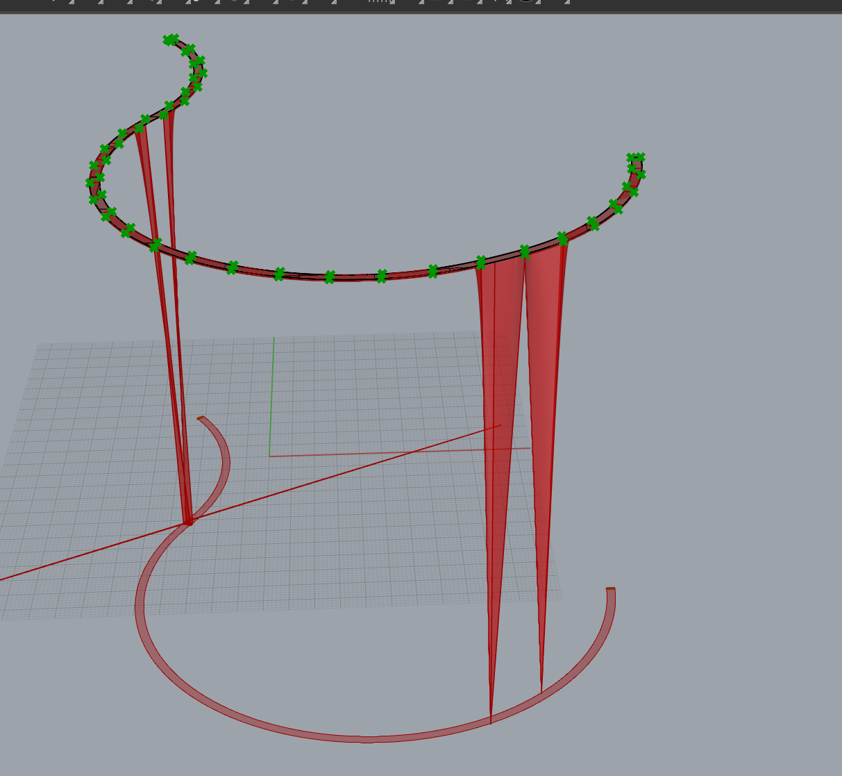
I model a surface as the desired top surface of a trail. Then i project it to Cplane to get the boundary, and extract point on the surface edges. But when i feed those to the toposolid component, I get a broken geometry, somehow there are points along edges trying to tie back to the cplane-where my boundaries are. I don’t know how to fix this, can y’all help me with it? Thanks a bunch!
did another test here, i get more confused. i use the same component structure for different surfaces and i have very unpredictable results and errors.
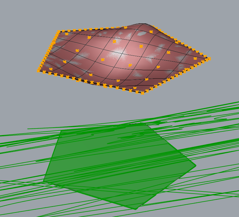
i first used a surface with very little edits, it’s created by exploded revit toposolid, just keep the top surface and I moved a couple control points, the result is normal
the next surface is created under a common condition in my actual workflow: I create a terrain model first, then i import the revit toposolid as a layout reference, then i drape a surface over the terrain, and split it by the revit toposolid reference. and i can’t get the correct geometry - seems like some points are trying to connect back to the projected boundary at its level, but why is this?
another test is using a more exaggerated geometry created by a sweep1, the rail is handdrawm with a limited number of control points, and the result turns out fine.
this test is also simulating my workflow: i created a terrain model first, then i drape a line as the alignment over the terrain model, then i create a sweep 1 using this alignment as a rail. but I get a red warning and some crazy graphics, the warning message says some points were out of boundary, but again, how?