I have been a long time lurker on this forum and have found so many great solutions so thanks to everyone who has helped me so far!
I have been trying for a few days straight to write a g-code sender for a 5-axis painting machine I have built. I am having an issue with a definition which generates correct axis values based on a plane defining the tool location I want. The A and B values are almost correct, but not quite. I have made a definition from scratch which does the inverse kin of 6axis arms, so I understand some things but thats about it for my knowledge on the subject.
I have looked at the scripts from 5axismaker, camel etc but am still having trouble.
I am student who is 100% self-taught with grasshopper and have not taken linear algebra yet (which would probably fix my issue) but I am looking to the forums to see if I can get some help before I take the course in the spring. Possible I’m also just making some stupid mistake.
So far I have had a great time with this machine, especially building a 3-axis g-code sender in GH and creating GH geometry to send.
The script is a bit messy, I am in the middle of cleaning it up and will post again ASAP with a simpler and annotated file. 5 AXIS SIM.gh (509.9 KB)
All the nested clusters make it a challenge to understand so let me ask two questions before digging deeper.
Why do you want the curve tangent at each point to affect plane orientation? If the curve were on a surface, I could see using the surface normal at each point to orient a plane for the printing tool, like the Evaluate Surface ‘F’ (Frame). But this curve is on a flat surface so why create vectors skewed away from vertical?
The tip of the “Pen” doesn’t touch the curve division points. Is that the problem you want to solve?
As I make my way through the clustered layers of your model, I can see potential for accumulated small errors. Computing pivot points and rotation angles, for example.
Two thoughts are jumping out at me.
Instead of passing vectors and points to your first cluster, why not pass the plane instead? At some point somewhere, the orange block holding the pen (and maybe the purple block attached to the orange block?) should know exactly the origin and orientation (the plane!) where it needs to aim. From what I can tell, that gets lost in transformations happening along the way to “Create Pivot point” and determine rotation angles to be used later.
Instead of passing all planes for the points along the curve, why not pass only the single plane defined by the ‘Sim Value’ of the animation slider?
In reply to your first point:
This is because I am using a paintbrush and I want to emulate the way a wrist moves, it is a very particular thing that I may not use.
Second:
Yes this is the issue I want to solve! I just want the AC values to be correct for a given tool plane.
I will try to refine later this afternoon with your plane-passing feedback. I can also expand those clusters and reorder to make the script more linear and hopefully easier to debug.
I guess my method is I just try things until I think they work, this is the first time this method has failed me!
Thanks,
T
I did some very meticulous refactoring. I realize that it can be unnerving for anyone else to touch “my code”, especially without being able to easily compare before and after, as is common with traditional text based programming.
I didn’t change any functionality at all though and it still works as before.
Moved the choice of point/plane to the white group, outside the cluster, and pass only one plane at a time.
Moved the first big cluster (with no name?) internal to the Simulation cluster, which itself was simplified by step 1.
I could keep going but better not. It’s how I understand code. Usually leaving old functionality intact, as I did here, while exploring alternatives and making sure that everything still works properly before replacing old with new.
Like this bit I did while composing this reply, replacing this:
You make an excellent point Joseph. I seem to remember when coding in assembler, basic, C# and a few others, there were various utilities to find the “differences” in code between one version and other and then highlight those changes.
Does anyone know of a utility that will do the same, or similar, in Grasshopper: show the differences or changes between one version of a script and another?
That most BASIC functionality doesn’t exist in GH and is very sorely missed.
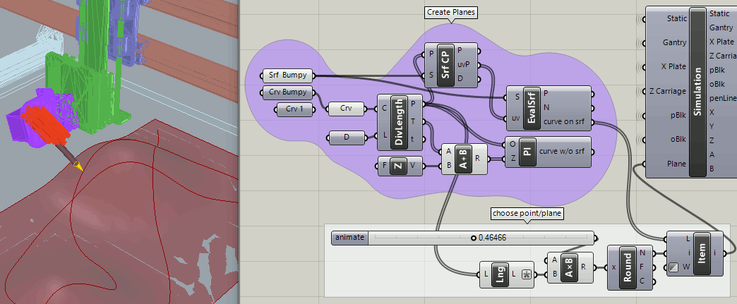
Here is a very basic illustration of where I was going with using the plane. The pen aims precisely at the point, problem solved! I know that’s not enough to generate G-Code but there are two objectives here: 1) to create a cool and accurate GH model and 2) to output the transformations required by the physical machine. But I like to get results fast and refine the details as needed.
I did this too with orient and even tried a little addition that added the error between the two to the bad line.
I know its not a good fix but it made the program slightly more accurate.
You are right about the output.
I did some research last night about breaking down the orient transformation output into rotations but got a little lost.
This view compares the ‘orient to target plane’ approach (with pen tip) to the existing centerline that misses the point (pun intended). It appears that the top ends of the lines are coincident but the angle is slightly off. I don’t want to trivialize this by making quick fixes but am pretty sure that it’s possible to work backwards from what we want to the rotations and offsets needed to get there. “Breaking down the orient transformation output” isn’t the only way.
I have noticed this as well, that the top ends are coincident but bottoms are not.
However, I think the issue is that the angle between the two lines is compound (correct term?) and needs to be split into AB angles again.
This splitting is where I am pretty sure the error is.
I just found this post by machinehistories on the legacy forum: https://www.grasshopper3d.com/forum/topics/5-axis-toolpath-calculation
Since I am not using an input surface I thought the method was irrelevant to my issue, but maybe I could take a leaf out of their book?
Possibly place a uv sphere around the target plane origin and evaluate the intersection between plane normal and sphere?
I don’t trust the unnamed cluster that generates the A and B angles because it’s too complex to understand at a glance. An old rule of programming was that procedures and functions should be readable and comprehensible on a single screen. In the old days, that was 25 lines of 80 characters. If bigger than that, it should be split into smaller pieces, though there were exceptions, of course. Later, it became the fashion that every function should be verifiable through “unit testing”, which got a bit carried away but the idea is good.
I’m not advocating a “fudge factor” but added one just for kicks and curiosity. The following settings, determined visually by comparison with the ‘orient to plane’ method, seem to fix the pointing problem at all points along the curve.
Almost one degree of difference in the ‘A angle’.
Left to my own devices, I would use ‘orient to plane’ for the pen, then orient the orange block to the pen, then orient the purple block to the orange block, etc. It might end up doing the same things as the mystery cluster but hopefully be easier to understand and certainly more accurate.
It’s a fascinating puzzle but I’m not invested enough to read about what others have done or dig much deeper into this model. I’ll let you know if that changes with a second wind.
Some of what I said yesterday was a combination of “Beginner’s Mind” and the proverbial five blind men describing an elephant by touch. This morning, I woke with a clear vision of the whole 5-axis geometry and a plan to start fresh. It is very simple and gave reasonable numbers right away (X, Y and Z are trivial). The A and B angles looked good but didn’t match the numbers from your mysterious unnamed cluster… This is why:
The mesh for the “orange block” is cockeyed, not aligned with ‘World XY’!!!???
So I created this repair utility to align it as best I can before applying my computed angles to it. What a silly way to spend time. How did that happen?
So I’ve now integrated that reoriented part with my new code, purged the mysterious unnamed cluster and it looks great at first, until I noticed that sometimes the A and B angles are positive instead of negative. I know why and am working on that.
A “big picture” question though: handling one point on the curve at a time simplifies the conceptual aspects, keeping in mind that the code should also work when fed all points (planes) at once. In the real world, isn’t there a timing issue moving from point to point?
I fixed my little plus/minus angle problem using the sign (+ or -) of the Dot Product(DProd). It all looks great!
Then I compared it to your original post yesterday. Other than the pen being more accurate now, can you spot the big difference?
Original:
Today’s version:(Nov30a)
I’ve been around the block a few times trying to understand how that happened and if I need to fix it, without any great insight. I think it’s likely that the original orientation of these two parts can be rotated to fix this issue, if necessary. The orange block (‘oBlk’) needs to be redone anyway to fix the cockeyed alignment mentioned in my previous post; my repair hack is approximate and it appears to slightly intersect the adjacent purple block (‘pBlk’).
5_AXIS_SIM_2019Nov30a.gh (497.8 KB) (NOTE: version below exports geometry: 5_AXIS_SIM_2019Nov30b.gh)
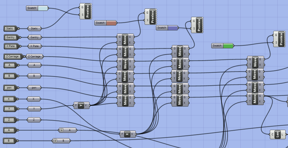
The Simulation cluster got much simpler to my eye. This approach appears to be sound and comprehensible, even if further adjustments are necessary. The gist of my waking thoughts is in these two groups. The first one gets X, Y and Z, the second one gets angles A and B.
I ditched “Pen Line” and replaced it with a numeric constant, ‘Pen Length’ (120.8659725) in a small white group with another constant found in the code, ‘Z_CONST’ (87.0).
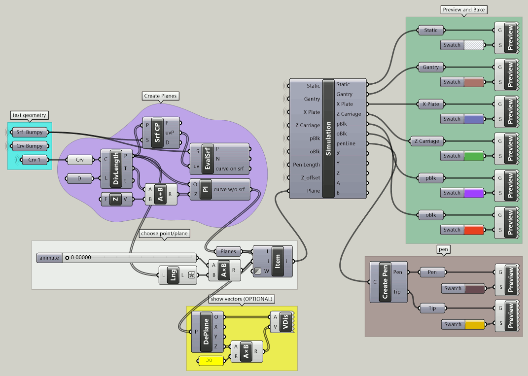
This is the full context with Create Pen being the only internal cluster remaining. (full size)
I think it would be a good idea to refactor a little further to export all the geometry so that Preview and baking of each piece can be done separately, outside the Simulation cluster.
P.S. Went ahead and exported geometry from the Simulation cluster. ‘Preview and Bake’ are now in the green group below:
Just looking at the images, this appears to be a much better approach.
It is possible the skewing comes from the location of the limit switches and due to this: the home location.
I have to run this command on the machine to get the brush perfectly vertical:
G0 B-77.5 A-88.8
I tried to work off of the actual home location in the original file but maybe I should just be running a command like this and zeroing the axes before I send the file.
Might make construction of the post-processing script easier.
I should have mentioned this in the first post,
Thanks so much for all this help, I will download the files tonight and have a look.
My apologies,
T
From what I can tell, all the parts are defined relative to point 0,0,0 - the “X” near the top right corner of this image with the ‘pBlk’ (or ‘A_head’?) and ‘oBlk’ (‘B_head’?) hidden. It seems odd that the ‘Static’ bed of the machine is oriented in the negative X/Y quadrant, requiring negative values for X and Y?
By the way, at some point in my refactoring I ended up with duplicate ‘A’ and ‘B’ inputs or outputs, one for the mesh parts and another for the angles. So for clarity, I renamed the mesh inputs to ‘pBlk’ (purple block) and ‘oBlk’ (orange block). Not ideal and should be changed. These IDs are repeated in many places now. What do you prefer?
Also, it occurs to me that the mesh geometry (which rarely changes) is largely responsible for the big file size. Maybe instead of internalizing them in the Simulation cluster, they could exist in a separate file to be copy/pasted and reconnected into each new version. I think R6 has features to read geometry from a separate file, which would be ideal? (We could use an R5 .3dm file for the meshes? It wouldn’t be downloaded unless it changes.)
Here’s a play with a curve on a bumpy surface. Works beautifully, with no changes required inside the Simulation cluster.
This is the default position of the mesh parts from your original file, before they get moved by the simulation. It’s obvious that the orange block is skewed substantially, rotated counter-clockwise (from above) around the Z axis ~12.5 degrees according to my “repair” model.
This (below) is after my repair,where I nudged it around all three axes to get the smallest possible Bounding Box. If you look at either of these views carefully, the purple block is also slightly skewed!!?? This isn’t correct.
It seems to me that, before they are rotated, both of these parts should be oriented so the pen points straight down, as well as being square to each other and “the world”. That would match the waking insight I had this morning that the default position is a World XY plane at the top of the pen (the pivot point for both, which moves in X, Y and Z). Angle A rotates the purple block around the X axis and angle B rotates the orange block around the Y axis of that plane. Right?
Anything else requires compensating factors in the code, like “x + or - 90”, which can get confusing. With both of these blocks also being skewed as they are, it’s no wonder you experienced some pain. Very cool model though, thanks again for sharing it.
As suggested, I extracted the internalized meshes from the Simulation cluster, which allows me to manipulate their default positions. This code (above the canvas) rotates the ‘pBlk’ and ‘oBlk’ around the pivot point to their expected positions if the pen is pointing straight down.
The second half goes one step further, offering a ‘QUADRANT’ switch (blue group) between ‘Negative XY (default)’ and 'Positive XY quadrants. Guess what? It makes no difference at all!
Ok so after finals I have had the chance to go through your file. Thanks again for all this help.
I Looked through your script and completely overhauled my script using your angle generation module. I also simplified the rhino file so any confusion from the original can be avoided.
Here is a simplified model and script from my original.
The reason I am still rotating the original pen line instead of using orient or two point line is because I am trying to test the angles for accuracy.
As you can see, it is still slightly off.
Any leads on this?
Tristan 5AXIS_AB_SIMPLE.3dm (3.4 MB) 5AXIS_AB_SIMPLE.gh (26.7 KB)