Are you using Plan and Section views or the workflow with the hidden display mode? Please, could you send me your model? I’ll check what is going on. You can post it here or send it to visualarq@asuni.com.
I have been checking your file. If you don’t want to show the intersection lines, I think the only way to do it for now is by applying a solid section pattern to slabs and walls. We already have an entry in our list to solve these kind of intersections automatically in future versions.
As for the opening edge line that you need to draw as continuous, I see that it is taking the linetype from layer 通り芯, but I think it should not be working like this because neither the wall nor the door are defined to take their values from this layer, so I am reporting the issue; I will let you know about this. From now, you can change the linetype in this layer in order to display this door correctly in the section view.
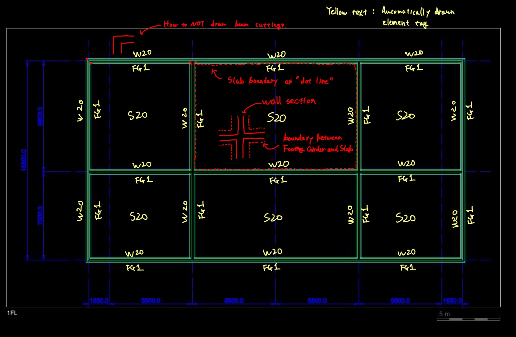
I understand why you need to avoid cutting beams in your drawing, but I think what you need here is a foundation object, which we already have in our list for future development. In the meantime I suggest you create those footings as wall objects instead as beam objects to avoid those lines.
If you need to display your footings with dot lines in your plan view, you can define the linetype you need from the style:
If you need to have these crossing lines only in the section view, you will need to draw them manually. Another possibility is that you create a Rhino 3D block where you have drawn these lines and assign that block to the corresponding door style, but this way you will see the crossing lines in the 3D model as well.