I’m trying to create waffle slots on a set of intersecting Breps but experiencing some buggy behaviour with the RegionSlits and also with TrimSolid
I got the definition from a solution by @HS_Kim which works beautifully in some circumstances.
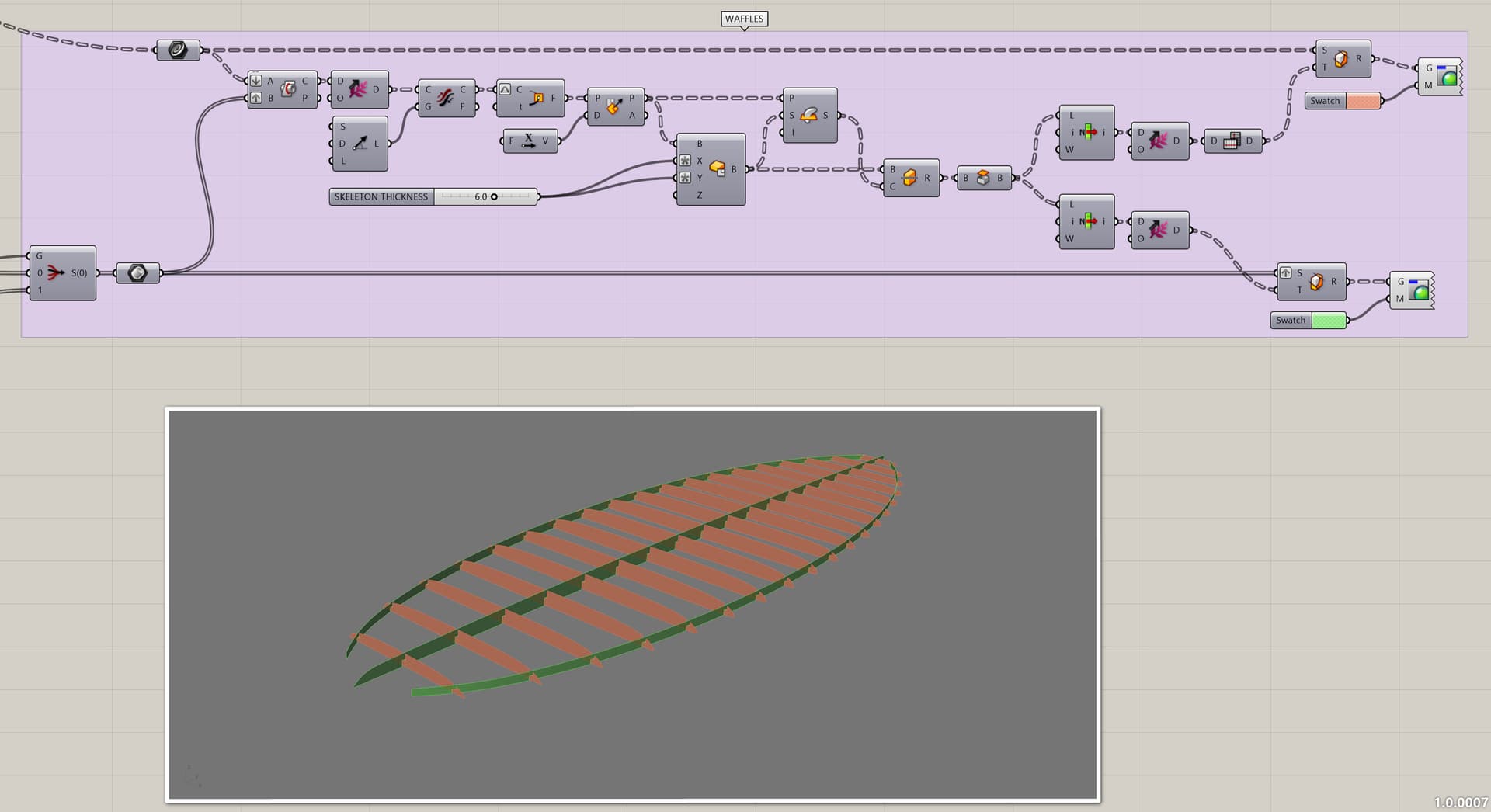
The components work some of the time and I can’t figure out why they fail. You can see here some of the sections get slots and some sections just disappear completely…
If I increase the number of sections in the Y direction to 13 they all work…
Similar to this topic which was using spheres as cutters in the TrimSolid component where the work around was to rotate the spheres to avoid surface seams coinciding.
I’ve tried rotating my cutters but it made no difference.
Its a similar issue to the RegionSlits problem I posted about.
Does the RegionSlits component use the TrimSolid method of creating cylinders on the intersections and using them as cutters?
This example has curved Breps in the waffle but I had the same issues with straight sections in both X and Y.
Is there some bad practice when using TrimSolid that I need to avoid (like paying attention to the cutter surface seams?)
Or is this a bug?
HK_SLITS_BUG.gh (75.8 KB)
Inexplicable workaround if anyone is interested…
HK_SLITS_WORKAROUND.gh (129.2 KB)

I think this is a tolerance issue. And the middle stringer might be what’s causing trouble.
Baking the three longitudinal surfaces, untrimming and retrimming the middle surface and finally set multiple breps in GH and all Trim Solids work fine.
HK_SLITS.gh (113.3 KB)
Thanks, that’s interesting. I sort of gave up on this. I was getting problems when I didn’t have the same number of intersections on each X oriented section. So, for example, if the sections at the nose or tail only intersected with the centre stringer then I would get problems with the Trim Solid. I assumed this was something to do with the data structure but I couldn’t see exactly what. I will post an example file later.
What can I do to test if this is a tolerance issue? Do you mean the tolerance set when I select the New Document template when I create a new Rhino file?
I also almost gave up, but had some time to kill while waiting for a large 3D scan to be processed last night…
How did you generate the curves?
In the end I used RDiff for the X sections instead of TrimSolid and it seems more reliable but its slow.
TRIM_SOLID_FIX.gh (126.0 KB)
Here’s the whole definition if you’re interested in the way the board is generated…
SUBD_BOARD.gh (197.5 KB)
I’m not happy with it really. I think SubD is a great way of getting beautiful, continuous surfaces but there’s a rounding that takes it away from the initial outline curve so if you want a board that is a specific length and width then you can create the outline that size but the subD shrinks.
Also, I want better control over the way the rail blends… It should be a sharp rail (edge of board) at the tail and blend to a rounded rail about 1/3 the way towards the nose.
I have 2 types of boards that I’ve called “Pin Tail” and “Square Tail” (That’s probably not what a real surfboard shaper would call them though!). I like the Pin Tail shape but probably wouldn’t make a board like this. The Square Tail shape is harder to control as it uses NurbsCurvePWK and is less intuitive to shape.
I’m doing this as I’m interested in making a hollow wooden board with the waffle skeleton internal structure that gets skinned with wood, then glass fibre. I’d like to be able to put the definition on Shapediver to get feedback from shapers using other surfboard design software.
I will probably have a def for each type of board.
This is interesting. I think boxes instead of pipes as cutters is a good idea. Personally I think I would replace some inputs with curves or points I could manipulate in Rhino instead of dragging a number slider. And then analyze the result with Grasshopper so I can check the design numerically.
Below is an optional solution for the waffles using TrimSolid
SUBD_BOARD.gh (179.9 KB)