I’m finding difficulty though in lofting the triangles together to create uniquely mitered edges that respond to their neighbors at a width of 3/4". The connections are intended to be a butt joint aka wood on wood connection. Attached are my files.
Instead of creating panels with gaps you’d have to create panels without gaps, join everything and use the Brep Topology component to extract the angle between two adjacent panels. Then orient all panels from 3D space to the XY plane.
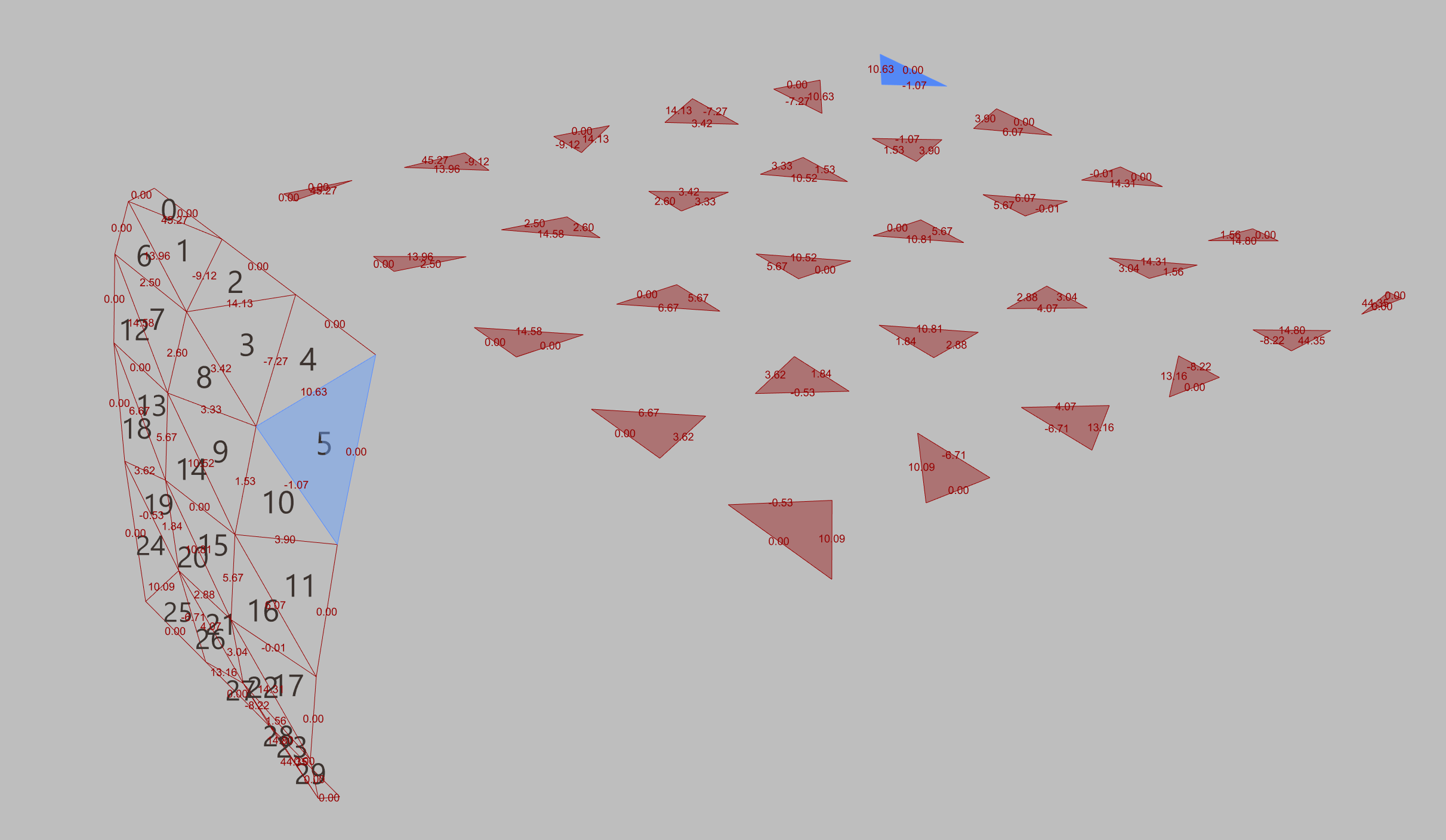
Below is a simplified version with less triangles and the input curves of your surface internalised. The Rhino file is not needed for this definition.
The angles shown are the angles between the face normals. Negative values are concave, positive angles are convex. You’ll have to divide those by two.
My triangulation is different compared to what you achieved with Lunchbox and I don’t know in what order your triangles will be sorted.
Our machine uses a 5-axis arm with a variety of drill bits to achieve a clean finish in a variety of ways. Right now we’re testing it out. Our CNC can cut unique angles for each of the triangles edges to acquire this seamless wood-on-wood attachment that is desired.
Our issue now is finding how to create/extrude the surface with a mitered edge in the Z-axis that responds to the neighboring triangle - similar to how 3D Voronoi patterns respond in unison when adjusted. Here’s a sketch that might help explain.
Yes that’s a miter cut and the same angle on both side of an edge. So x / 2….
Depending on the substructure used for this project, you could also cut all panels with the same angle.
Anyway, one way to create the panels is by extruding the edges a bit too far and use a C# script with Rhino.Geometry.Brep.CreateSolid
This works for the stripped example. I did not eliminate the intersections at some of the corners. This could be automated but might be an overkill, depending on your machine and CAM.
I took a stab at the problem. One way to ensure zero-gap is to join faces into a mesh and offset said mesh. This however won’t guarantee constant panel thickness. To do so, one further step is required:
. offset to a greater distance than the desired thickness
. make an extruded Brep of each face and its corresponding offset, using a loft to create the connecting perimeter
. trim the Breps with the face planes at the desired offset distance
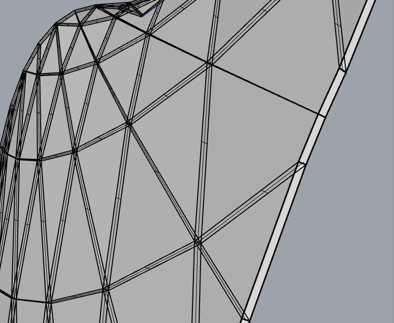
In this visualization red indicates the non-planar surfaces
Unless you have a torsion-free geometry to begin with, perimeter faces might be non-planar, and to maintain constant panel thickness you will have some uneven situations on one side, like these:
Be aware that in yours and @Rajeev2 method the panels do not retain constant thickness (which I believe was required by Tristan). Just offsetting the surface and repanelizing it does not guarantee that the panels’ front and back faces are parallel.
See this image where I replicated it (the numbers are the angle of the unrolled panels’ top face normal with Z - it should be 0 - also see the non-horizontal condition in the right viewport):
The solutions with lofting create no-planar miter surfaces, which of course can be milled but I don’t think this is very efficient compared to cuts with a 5-axis saw.
I haven’t looked at your files or any of those who replied with solutions. I’m confused about the 3/4" gap between them? Is that gap only for the “unrolled” CNC layout?
Good grief I don’t have Lunchbox so looked at your Rhino file to find that most of your layers are empty except for ‘Layer 07’, which has three sets of what appeared to be triangular surfaces, so I started with one set of them… 270 breps.
It took me a long time to realize that these are extruded surfaces, not the triangular surfaces I want.
If you (@Tristan_Ahlquist) can internalize the Surface param (output from Lunchbox?), I’ll take another look, unless you already have a solution.
P.S. I did some additional work to isolate the two largest surfaces of each brep and sort them by their X position, assuming that one is the base triangle and the other is the extrusion. When I zoom in I see gaps between these surfaces. Why?
Martin / Alessio / Rajeev / Mohammad - Thank you all for the quick responses and helpful edits to the script. You all absolutely rock for taking a stab at it. Very impressed.
The thickness of our 12 ply Birch is 3/4" = The constant thickness I’m looking for in each panel. @Joseph_Oster Preferably each panel will be fastened as a but joint with zero gap between. My desired method of joining panels is the “Lamello Zeta P2 P-System” seen below
Upon reflection… It seems unlikely to have a truly flat connection between panels… or even a flat surface from the secondary surface from the loft for that matter. IMO this could still work if panels are glued together at seams or fastened from behind.
Would be really interested if ya’ll had better ideas on how to make a seamless “Triangulated Blanket” surface that had no curves between joints. A direct panel-to-panel connection. Not married to just triangles either. Is a secondary structure inevitable?
Tristan, it’s right there. Just keep in mind that connecting all these panels with Lamello Zeta also means you have to assemble adjacent parts in perfect perpendicular direction. Zeta is good for anyting orthogonal but what you’re attempting here will be very complicated if not impossible with Zeta.
The miter surfaces in my definition are planar. But if the backside is never visible why don’t you cut all parts with let’s say -20° or -30° and use some good adhesive to glue all parts together using a waffle sub structure?
If you’re not married to the exact surface shape either you can try to approximate a panelization to a conical (torsion free) mesh, which would ensure planar thickness faces.
See this post by Daniel Piker for example:
He’s making the example with planar quad (PQ in short) meshes. Planarization and, ahem… “conicalization” (not sure if it’s a proper term) will move some points away from the original surface (there is a way of constraining the edge points to maintain the portal shape though), and the end result will depend on panel size, etc., but, if size and angle between panels remain within the interlocking system constraints, you should be able to use it without secondary structures.
This is a very laborious flawed effort using Anemone to trim scaled offset triangles. It has four flaws where it appears to me that adjacent triangles are so close to co-planar that their intersections fail.
The clutter at the bottom left of the first image is diagnostic output that could be hidden. My method for examining each offset triangle is to disable both loop components (start and end, orange group) and move the wires connected to FastLoopStart ‘C’ (Counter) to the integer slider in the yellow group. This allows me to access each triangle separately to see its intersections.
It takes the loop ~21 seconds to complete so there is a delay when opening the file or changing parameters. Not shown (because I just wrote it) is a simple ‘“unroll” / layout’ group.
@martinsiegrist
Agreed - Lamello system along a curved system isn’t the answer here and something I doubt could work properly. Our team favored this system due to the speed of production → reduction in lead times. A -20° cut upon a waffle structure / foam backing / manually attaching torsion sides with adhesive are our next investigations.
@ale2x72
Thank you for the reference this is great help. In square formations this might seem to work actually.
@Joseph_Oster
Thanks for taking a stab at it in another direction to validate the curved connections. Agreed - at such a small width, a mitered curved would be time consuming.
What “uniform angle”? Especially since some triangles appear to require a reverse angle on miters. Might as well just make the edges square and deal with gaps, eh?
As an afterthought, I added back components I didn’t use (yellow group at the bottom) that shows “dihedral angles” between faces, which range from -32.934998 To 17.201252 degrees with an average of -1.705997 degrees. The sorted list shows quite a few that are ±5 degrees or more.
I also modified the ‘“unroll” / layout’ group to use a grid:
P.S. Come to think of it, those “dihedral angles” in the yellow group are angles between face normal vectors so miter angles would be half of those values? The range is -16.5 To 8.6 degrees with an average of -0.853 degrees? Triangular Blanket Extrusion_2023Aug28aa.gh (46.8 KB)