I have modeled a curvy soffit under my canopy to cover the beams. I want to use the ‘Tongue and Groove’ technique to build it (1x4inch or 18x92mm). Basic instinct I went with ‘contour’ in Rhino but it doesn’t keep the dimensions equally.
The trouble is that you have 15 surfaces and two polysurfaces, most of them irregular, so it’s like strip planking a boat but much more complex. A finish carpenter/craftsman might pull it off but in CAD? No.
@Joseph_Oster Thank you for getting back to me. I’m aware of the complexity of the shapes. I just wanted to see how it would look like. I’ve tried the contour in a vertical way and it did the job for now. Do you think we can use CAD to have only the lines?
Traditional tongue and groove probably won’t work, though it might be possible if you can have your parts cut on a 5 axis cnc router.
This kind of profile on the edges of your parts, on the other hand, seems like a more flexible solution:
The inner part of this form, as you can see, is more forgiving of angular variation than tongue and groove is.
That said, from experience building paneled spaces with odd angles, the only way pre-cut parts are going to fit is if your framers do a rough frame and then shim their way to perfect using lasers.
There may be another way to get it done. If I can see it in context to get a better idea of the scale, I might be able to help you. Another option might be to use large kiln dried architectural grade framing members (4x12s or something like that) to piece together after cnc carving. Likely it’d be a two sided carving: one side gets your bevels, then you flip and carve the compound curves while the parts lie flat on their backs with any undercut bevels already dealt with.
Or maybe you contour them perpendicular to how you did it, and use a stack of a lot of plywood to get a very stripey version of the form.
If you look at his process section, you can see that he does model in CAD before fabricating.
I think it would be fairly straight-forward though. You just need to have the surface that you’d like the pieces to be conformed to, then divide the length into strips.
Yes, Matthias Pliessnig’s work is based on a single surface where the cross-section frames are relatively close to the same length, allowing strips of constant width where the gaps don’t become too large. Much easier.
There’s also a question of scale. At theater size, or pavilion size, using spaced 1x1 strips or dowels, or maybe even larger is workable because you’re not bending them that much, at least not in the forms we’ve seen as examples.
At the scale of a room within a residence, you’ll be more limited. Looking closer at his site, the smaller applications of his technique sure look like they must involve some steam bending. And also, he appears to be notching his ribs and using some kind of blind fastening technique. All of this is a whole lot of very skilled work.
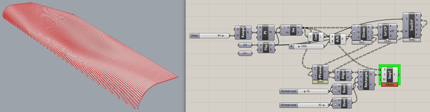
@TheCyclist, @Max3@Joseph_Oster I give up with T&G, I thought it would be easier but it’s not. So quickly I’ve tried to do Matthias Pliessnig’s approach to one of my surfaces but I need a help on a few things.
I wasn’t able to control the direction of curves. I used Unit Y but it’s not parallel to starting point/line. Blues what I got but the magenta direction is what I’m looking for. I don’t know how to get that direction in Grasshopper.
Well, your surface is poorly formed in several respects. It is a trimmed surface which makes it a problem to split with isocurves. And it has a kink (hard spot) in one of the long edges. These two factors create a LOT of extra work.
Your cross-section curves differ in length by quite a bit so spacing fixed-width strips evenly doesn’t work well without large gaps. It’s really quite a mess and I’m not sure it’s worth the trouble to pursue further.
P.S. And your unit values are extremely large!? Your surface is ~27,000 units long.
@Joseph_Oster I see, what if I extend my isocurves to the same length and loft them as attached would it help for grasshopper script? Trimming on plan view can be done later…
It’s in mm, that could be it. in overall elevation is almost 100 meter long.
I can’t look at this again today. It’s a pity to do all this work and get a shoddy result, as I knew I would. I hope you’ll read all my comments on this thread and rethink your surfaces. Matthias Pliessnig’s look great because he created his base surface CAREFULLY.
When the surface is badly formed, the result will be ugly.
One of the troubles with a surface 27 thousand units long is that it’s very difficult to see perp and surface frame icons and know how they are oriented.
Good luck. This (below) is the wrong way to go about this. Deeply wrong!