Tongue and Groove

But this isn’t done. I’m very interested in figuring out how to make it really work.

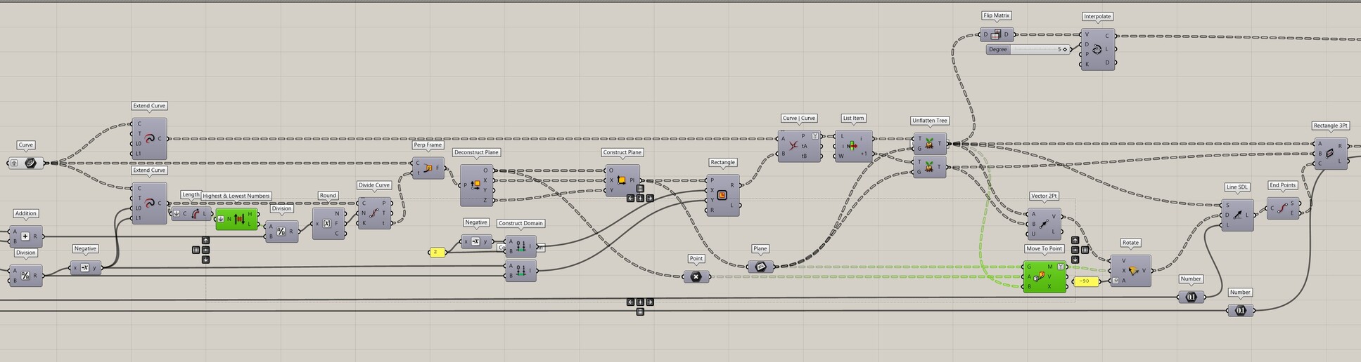
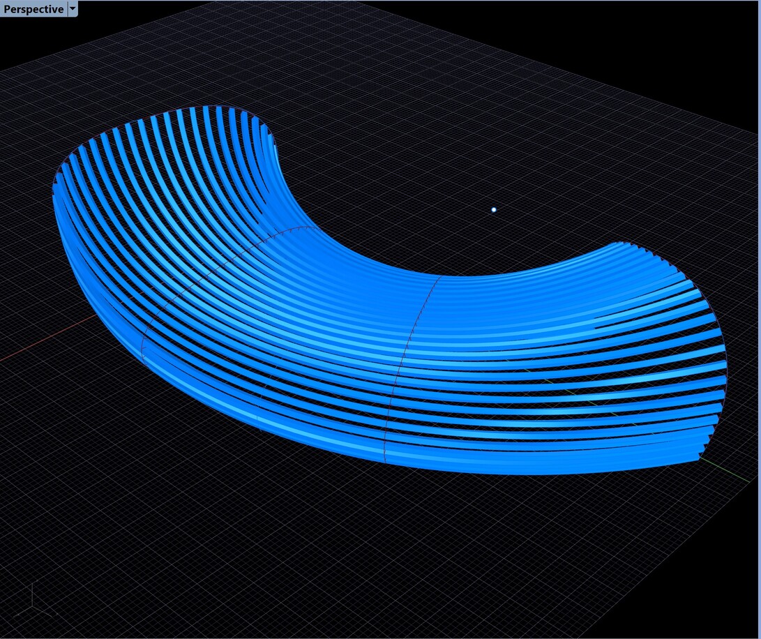
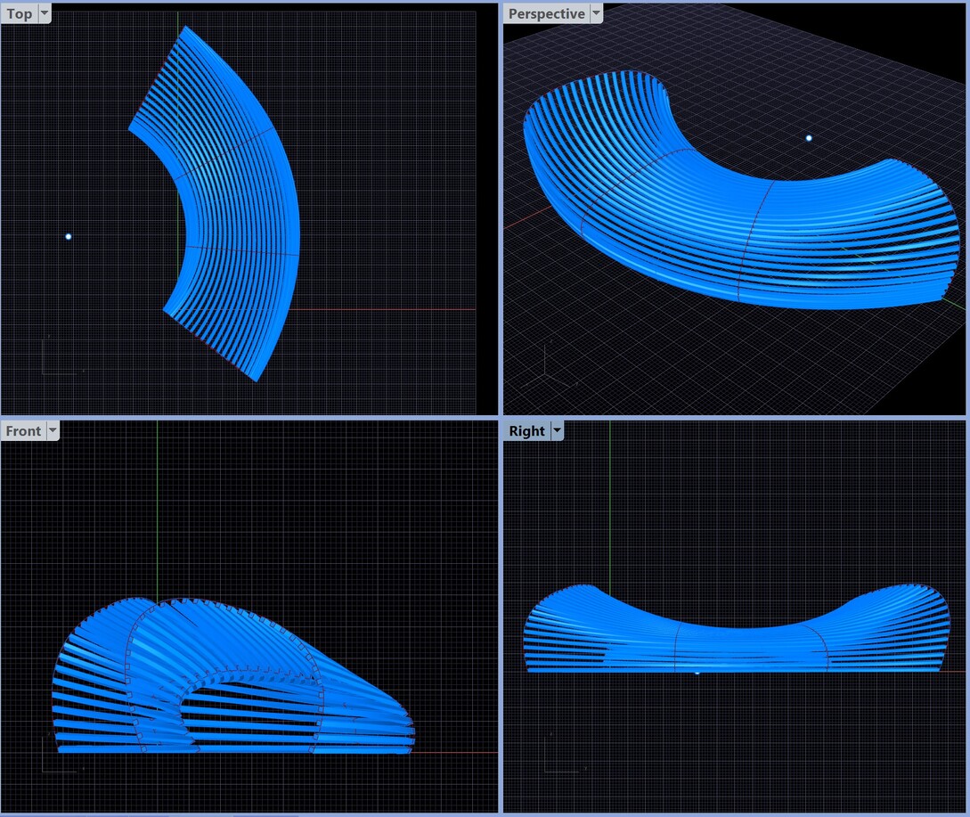
One thing I see is that part of the problem in the latest definition may be too many ribs.

Also:

-rather than guessing our way to the correct number of decking strips, we should base it on measuring the shortest rib and dividing it up base on the minimum acceptable spacing between strips.

-If the goal is ultimately to construct this with physical strips on simple 2d ribs, the rectangles need to be generated from lines with both of their endpoints on the rib curve. If you don’t do this, the gaps between your decking will not conform well to the flow of the ribs. Also, as you’ll see in the definition, you’re limited in your spacing by collisions that can happen between strips when your gaps get small near tight convex curves.

My GH experience isn’t great, but my getting weird stuff built experience is pretty good. So rather than tackling previously posted definitions, here’s how I’d do a single rib’s worth of rectangles, from the perspective of wanting to make it buildable: Ribs and Rails.gh (23.6 KB)

My next step in trying to figure this out would be to test the difference between using lofts and using sweeps created by interpolating curves between points taken from the rectangles.

After that, there’s the question of rib placement and spacing. Would each rib would be planar of is there budget to make them not planar? (I think my humble definition will also work on non-planar ribs, if you can get them fabbed) Would the ribs collectively be on parallel planes or is it worth slanting them in places? Will the be CNC cut notched wood, or will they be bent metal?

The others are right that a better formed surface would make it easier to derive a solution from isocurves. I think that from a practical construction perspective, you can probably get a good approximation of the surfaces you drew by extracting ribs strategically rather than in a uniform way. Ultimately, also, modeling strips that perfectly conform to your surface curvature won’t help build this. You’re beholden to what the strip material can do, how much it will bend and twist, so model based on that, and maintain the cross section as much as possible.

Using isocurves isn’t necessary but the smooth cleanliness of Matthias Pliessnig’s models will never be matched unless the underlying surface is constructed very differently. GIGO (Garbage In, Garbage Out).

The “curvy soffit” with disjointed surfaces and irregular edges isn’t appropriate at all.

I agree, particularly in this way:

If the variations in the rib curve lengths are not smooth, the results won’t be either. Like, if one is 2% longer than the previous one, and the next one after that is 1% shorter, and then the next is 1% longer, etc, it’ll just look like it was poorly executed.

That trait, of course, comes from a better formed surface. It might also come from strategic, uneven rib placement along the existing surface, which, in turn, would effectively create strips running along an approximation of a better formed surface. The core of the GIGO here is a curve interpolation point problem.

Took another pass at this for fun.

Used my own surface and manually chose rib curves I thought would work well.

This definition: Ribs and Rails.gh (42.7 KB)

  • decides how many lengthwise strips to use based on the length of the shortest rib and your chosen strip width and minimum gap.
  • aligns cross section rectangles so their outermost vertices are always on the rib curve.
  • uses Sweep1, because it got me better results than loft. (sweep 2 broke a lot so I gave up on it)

There are some things I did in here that are a tiny bit imprecise in order to fix bugs. The cross section widths can vary by a very small fraction of a unit. And the uppermost strip extends a tiny bit beyond the end of the ribs because if I didn’t use extend curve as a bug fix, the top strip sometimes disappeared. All of these are a few 1000ths of a unit at worst.

Things it needs:

  • a clash detector for the final solids
  • an easy way of using a guide curve to cleanly cut off the ends of strips midway along a loft

Your results look great. Wish I could run your code…

missing

I didn’t even know move to point wasn’t standard. All it does is move geometry from a point to another point. Seems like something that could be easily clustered out of native components. I just used it to move my perp frames to another spot so I could use them as axes to rotate around.

Highest and lowest is only there to detect the shortest rib curve quickly. It literally just picks the highest and lowest numbers on a list. Again, there’s probably a two component native solution.

Bifocals is there because I like to be nice to beginners, it’s not important to the function.

I’m aware of all of that but without a screen shot of your canvas, I wouldn’t know where replacement clusters go because without the plugin installed, I just see gaps between disconnected components.

offending items highlighted.

gotta clean up after dinner, will swap in those native components later.

Thanks.

HiLo_mov2ptl_2020May21a
HiLo_mov2ptl_2020May21a.gh (6.0 KB)

P.S. Slats appear to be thin and distorted in cross-section. Maybe I made a mistake?

HiLo_mov2ptl_2020May21a2

Yup, the clusters are correct but I had input wires crossed on mov2pt. Very nice.

I swapped in the native components but apparently you did too.

The only thing that messed with me in figuring this out was that the curve curve intersection component broke my trees and it took a minute to realize how easy it was to put them back together.

Still annoyed I couldn’t get sweep2 to work. it kept deleting a strip. I’m not sure how much it matters though. The real subtle difference here between loft and sweep1 is that sweep 1 allows for a degree five curve and loft does a degree three. So with four ribs, sweep1 gives a single span.

If some of the ribs became a lot longer than the shortest rib, then it could be taken a step further to place an additional strip between two once enough space was created.

It doesn’t look like Matthias does that in any of his works.

It looks like he constrains his rib lengths. I’d be interested in learning how to do that with an algorithm. Probably not hard to adjust the length of tweened curves to keep them within a certain ratio of each other, just by scaling, and it’d probably yield good looking results.

Improved it. Making the rectangles by using rotation relative to their rib curve to get the third point was bad. The third point should be normalized to our source surface. Achieved that using offset surface and surface closest point. The previous version failed badly with more extreme curvatures. This does better.

Ribs and Rails.gh (41.8 KB)

5 Likes