Give this one a go, feel free to improve, redesign, or copy directly. I’ll post my wireframe in a few days… (don’t want to give away too much too soon…)
Hint: I started with a single strip of faces. But there are MANY different ways of getting there.
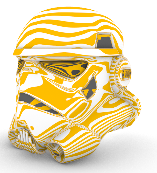
I used my own helmet as idea. A different one then the example of the challenge, but modeling a helmet that comes close to the pictures of the challenge example is to difficult for me.
Helmet… that’s a wide topic isn’t it?
I always wanted to do this so I might be bending the rules a bit, anyway here is a work in progress image.
It’s tedious work and requires modelling of bits and pieces and stiching them together, but it’s coming along.
The things I miss the most is:
have join work like append, so I can hit Ctrl-J and get autosmoothing of the edges.
A mini-bridge that only takes two edges as input. Again for fast adding of faces.
extrude an edge along an edge. For fast adding a face.
Like here, if I want to add a face here then I now add a new single face and then append it:
And the insert edge inserts in two directions IF the edge hits an open area:
I don’t want that and would prefer if it recognized the kink and stopped there.
Id rather do it in two operations if I need it than not being able to just add alon one side.
Also, if Insert edge is ran and filter is on surface then it is not possilbe to select the edge. The tool should ignore selection filter since the tool spesifically asks for edge.
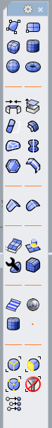
I also put the icons into a new toolbar so I don’t have to swap between sub d and normal mode all the time. And I organized them so they are quite logical to use when I work.
Thanks Kyle.
I could not have done this model in Nurbs, would have taken me days. This helmet took me about 4 hours to model, while in a learning curve.
There are two things that I do not like about SubD, but I have understood that these issues are fundamental, and I will have to live with it.
_Inserting an edge in an object changes the shape of the object. I always try to minimise the amount of vertices, but when I discover that I have to insert extra edges, often I have to correct the unwanted changes of the object around the new edges. See how this circular shape gets disrupted after splitting a face :
I use SubD modeling mostly for shoe last design ( https://www.youtube.com/watch?v=gXFxQoMuXW0 ). To match parts of the lasts with footscans, I pull specific groups of editpoints to the footscan (a mesh).
The new SnaptoMesh command is also very useful. But I do miss the option to drag more than 1 editpoint along the mesh, with all the selected editpoints snapping to the mesh (as “retoposnap” in
Tsplines).
Sometimes I get confused when selecting an object does not work, because I did not realize that I had a selection filter enabled.
Is it a good idea to have some sort of notification active, when a selection filter is on? Maybe a colour change of the cursor?
Same problem for me with SnapToMesh enabled. Not realizing that leads to this cursor: , and then it takes some time for me to understand why this happens… ( I did store the command to disable snaptomesh in the same button as RightMouseClick b.t.w.).
When the Gumball is set to “align to object”, all the selected grips/edges/faces should move in the direction of their normals when dragging. Now I have to (also) select UVN dragmode to make that happen.
I do have more wishes, but they are already mentioned before by others on this forum, like
: the option to extrude multiple edges in the direction of their normal.
: the option to have more then one segment between the original object and the new when offsetting an object as a solid
More wishes will pop up, I will let you know.
SubD is now (although in WIP) already a great tool for me, even better then Tsplines was. I could not make my lasts in CAD without it.
Thanks for the feedback, I see bridge works like you say, nice, but I still would like to not having to preselect, so the wish stands (But I will adapt your workflow for sure!)
I mean when I model along an existing edge I want to be able to sweep1 one edge of a corner along the next. (See example above). Does that make sense? That way I can quickly model a crease along an edge and fine tune the points as I go along.
Edit: Here is an example of where I have deleted a few faces and want to build along the edges. Using a sweep1 like feature would be just what I need:
yep, fading creases is something we do not have, and afaik will be some time before we can sort that as it’s a limitation of the catmull-clark back end. @dalelear can clarify that much better than I could because he’s smarter than me.
Insert edge with an exact mode that does not change the shape is also in the works and Dale can give more info on that as to it’s timeline or even it’s possibility.
Can you expand a bit on your snap to mesh wishes? any models, videos, or more detail would be helpful as this is a feature we want to get right for a number of reasons.
Nice suggestion for a “filter mode” for the cursor to indicate a filter is on. I’ll write that up.
can you show a quick screen capture to demo your align to object issue? Does just using drag mode uvn make that happen with the gumball set to world?
Multi extrude via normal is already logged, I will write up the option to add edges when offsetting-
Great to hear we are on the right track so far, thanks for using it and keep the comments coming!
When drag mode is set to UVN, regardless of the alignment setting of the gumball or the amount of selected grips, all the selected grips move in the direction of the normal, when dragging the blue arrow of the gumball. This works as expected, only the gumball has a location and direction that is a bit confusing.The blue arrow does not point in the direction in wich the grips will move.
When the drag mode is set to Cplane or World, and the gumball is aligned to Object, dragging one grip works as expected, it moves in the direction of the normal. Also the gumball has the right position and direction, the blue arrow points in the direction of the normal. Everything is fine. But when more than one grip is selected, dragging the blue arrow results in a movement in Z direction, not perpendicular to the surface. I would expect that dragging the gumball (aligned to object) gives the same result as when the drag mode is set to UVN. Also I think it would be better if the gumball is positioned at one of the selected grips, with the blue arrow pointing in the direction of the normal, as it does when only one grip is selected.
The direction of U and V is not ambiguous for SubD objects.
I guess a normal direction arrow wouldn’t be amiss. As with surface points you get a UV direction helper. Since the ‘N’ handle is only most relevant in the UVN drag mode, maybe it should appear there
Ctrl+Drag when in UVN mode also will move those points in their respective normal directions. I may be wrong, but I actually don’t see that documented. I read it on another thread.
Hi All
Litterally 10 minutes of modeling. I know it’s something completely different when designing “for real”, but for really quick concepts and shape studies, this is great fun!