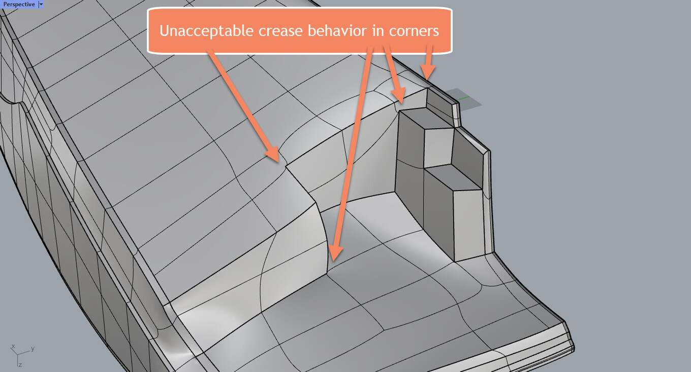
Press Tab key (or type SubDDisplayToggle) to switch SubD display from smooth mode to flat mode (a.k.a. box mode). Take good look at your model - I bet it is messed up in those spots.
It appears that behavior is inherent in SubD where three creases meet, two exterior and one interior,.or two interior and one exterior. Simple example attached: SubD Funny 1.3dm (1.9 MB) Added: The behavior does not always occur. See the post below.
SubD appears to have some limitations for precision modeling of surfaces.
Hi Kyle,
Thank you for your input. I am testing now bevels and it is a soft crease then. The same as soft- and hard creases in good old T-Splines.
This might work and still I think that creases should also work if possible.
However, for this specific motor boat example I see that SubD is then better for the superstructure as the rough hull can perfectly be modeled with Nurbs strakes and then add the aft body propulsion details later separately.
What you’re really looking for is Edge Weighting where by selecting an edge and basically influencing how it affects the surrounding topology. Think of this as like tangency/curvature influence when modeling with NURBS.
In most other SubD/Polygonal software this is possible (Blender, Modo, Maya…etc). The Rhino team knows of this “limitation” and have said as much. If there will be the addition of this process is kind of a TBD right now. So basically it’s not a limitation of SubD modeling as much as it is just showing where things are with how it’s currently implemented in Rhino.
Keep in mind you can crease in SubD, then convert to Nurbs and fillet or blend the resulting Nurbs surfaces to develop further.
Subd “filets” are not super precise… and in a lot of cases you are better served leaving the fiddly transition surfaces to be done in Nurbs once the main form development is done in SubD.
Remember, SubD and Nurbs play very nicely together. Make sure you are using the right (and best) tool for the intended job.