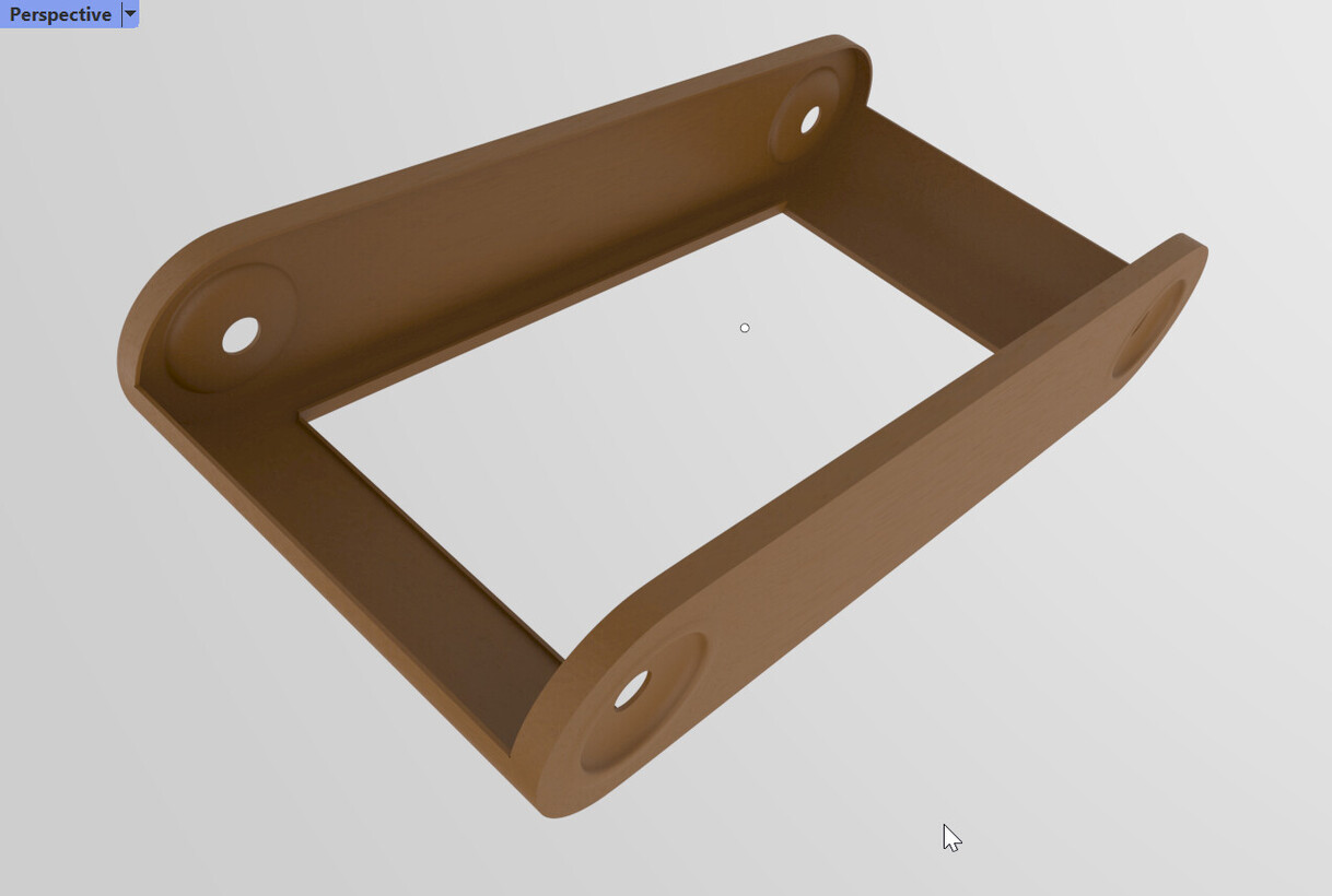
I’m hitting a problem trying to model accurately the leather skin of an old camera in SubD. It’s basically a box with rounded ends and various indentations and cut-outs:
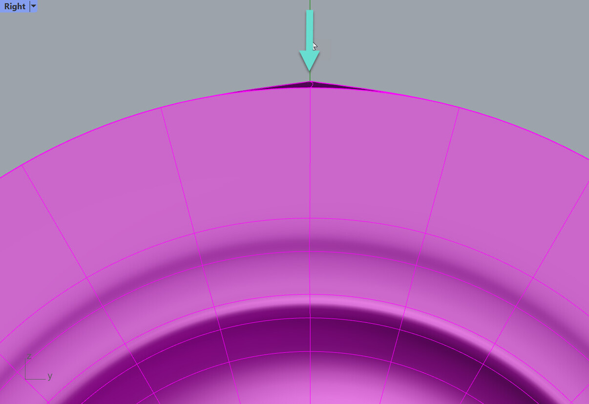
I have used quite a lot of segments for the rounded ends and succeeded in getting accurate circles. However, after making the cut-out for the camera back (the bigger one), with creased edges for the opening, the shorter edge of the hole pops out slightly and I get a small but nasty artefact around the corner:
Just a couple of observation.
If the edge loop at the problem corner would go around instead of looping into other parts of the geometry… it may help, at least it will let you add another edge to smooth the transition from crease to no crease [if you crease that one edge the nasty blimp is gone [but you have a crease where you don’t want it]
Unfortunately I don’t have a lot of scope for bevelling this as I’m trying to reproduce a real object which, selfishly, has nice square corners.
I’m interested to know whether this is a fundamental limitation of SubD, a Use Case that hasn’t yet been catered for in the Rhino SubD development, or something that will work better with a different approach (e.g. @Akash’s suggestion).
On a wider note, I’m coming to the conclusion that making a model of a real item can actually be harder than designing something new.
Yeah, it was a deliberate decision to explore the potential of SubD within various aspects of this model as a learning project (and labour of love). And there are some organic cut-outs to come that I couldn’t readily achieve in Nurbs so this seemed like one of those opportunities… Actually, I shouldn’t really be doing any of this in Rhino - 3D-Coat would be Dr Who’s sonic screwdriver for these screws - but trying to push the limits occasionally is the best way of understanding where they are. And then I’ll probably do it all again in 3D-Coat just by way of comparison.
Jeremy
Footnote: “When all you got is a hammer” from Blackbirds album by Gretchen Peters - powerful song.
Agreeing with Kyle here that this is something that should be done in NURBs.
Adding a wrinkle: I often use NURBs for most of a part and use SubD to get started on more complex curved surfaces within a part, later converting to NURBs and joining with the part. In this case, though, this really looks like straight NURBs.
Thanks Max I appreciate the thought, but as you might infer from the second screengrab in the preceding post, I have a nurbs version too… As I said to Kyle, I aim “to explore the potential of SubD within various aspects of this model as a learning project… …trying to push the limits occasionally is the best way of understanding where they are”.
Thanks to everyone who has contributed their ideas on what to do with this modelling. It’s the willingness of people to chip in with their ideas that makes this forum a very special place.
However, I’d still like to know if the vert popping up, and the artefact that goes with this event, which seem to be caused by the presence of a creased edge cut-out, is a fundamental behaviour of subd that cannot be prevented or just something that the subd devs haven’t got around to addressing yet.
typically speaking, a crease will have some difficulties to work thru. that’s why I typically crease early, then change them to a bevel once I have the early heavy lifting done.
I personally don’t like creases as they look “fake” in renderings… (real things typically don’t have perfectly sharp edges, seeing them is a dead giveaway for CGI)
BUT, I do use crease when I’m laying stuff out and want to keep track of what edges are going to be sharper than others.