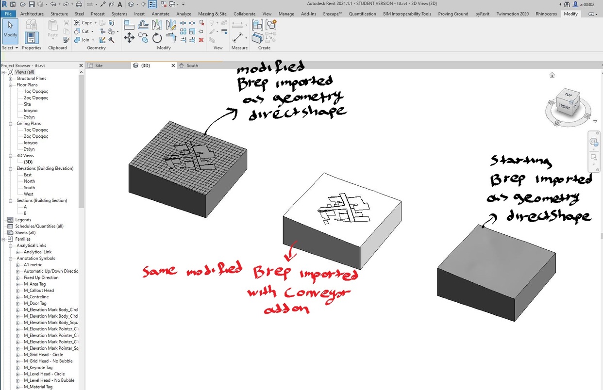
Hello. I have modeled a site in rhino as a closed poly surface. I importing it in revit using geometry direct shape component. Everything fine.
Then I modify the created site and I place some pads , roads and sidewalks. The result is again a closed polysurface. I reimport in Revit using again geometry direct shape component. Now I have a problem because inside revit the surface isolines are visible. The isolines not the creases. I tried importing the same surface using conveyor add on and I am able to import it correct. What’s the problem?!
I attach an image of Revit file and also the rhino file with the first created site and the modified one.
RevitInside|690x446
Probably exceeded the short line tolerances for revit and it needed to convert it to a mesh.
What is a sort line in Revit? Is there a way to check for that type of edges in rhino?
So you think the conveyor plug in modify the closed polysurface before sending it to revit? As I have seen in the bars is export the polysurface as a sat file.
Thank you.
The latest RiR should throw a notification and highlight short lines when using the direct shape component.
Conveyor has some internal processing before going into revit that creates that cleaner object.
The best route would be to try identify what is going on with your shape. Keep in mind document tolerance in Rhino and distance from origin, as this has a big affect on geometry.
So I update Rhino inside and now you are right when the grasshopper component became orange or red the result is a mesh.
But I must say that my geometry is pretty clean.
I tried again from my starting geometry which works without problems.
Even after the first boolean difference operation, the component became red or orange. I saw warnings out of tolerance. I tried a specific boolean difference operation many times. With rhino tolerance 0.0000001 meters the component became red. If I add another 0 in rhino tolerance then the boolean operation fails. So its nothing that I can to make it work.
I tried to make the boolean operations in AutoCAD. Then I import again in rhino and again the same result. But if I import the AutoCAD file in a Revit generic model family then it works.
Totally confused.
Does anyone know in what tolerance Autocad work?
If it’s not a tolerance problem then what?
When I import my starting brep as geometry direct shape and have no warnings in grasshopper and isolines is no visible in Revit, if then I export the Revit file in dwg the result is a 3dsolid in AutoCAD.
When I import the modified brep, I saw isolines. Then if I export again in dwg the result is a body in AutoCAD. I don’t know what is an autoCAD body but if I import this body in Rhino the result is a block and if I explode it I have an open polysurface.
So it’s all about tolerances which I cannot solve.
Now as I said if I import the same geometry with the conveyor I get the desired results. But when I export again in dwg the result is also a body. So I think the only difference when importing with the conveyor is that the edges are not visible. Is there a way to hide edges with the grasshopper?
I believe conveyor has its own mesh interpretation, as mentioned in their “novel” method of meshes into revit.
Yes i have seen it. But it must be something that revit or rhino api support.
Its not a separate program. Its an addon.
Hi,
An AutoCAD BODY is an open polysurface in Rhino, if it was planar it would be a REGION in DWG and if it is a closed polysurface it become a 3DSOLID in DWG.
The thing here is that Rhino.Inside is trying to transfer closed polysurfaces as closed solids in Revit and it fails because there are shared edges on some surfaces that are out of tolerance (absolute tolerance in Revit is 0.0005233832795 feet or 0.000159527224 m).
If that process fails it tries exporting as SAT and importing the SAT back to Revit.
Is SAT not working on your case?
I am able to import SAT files into Revit, but the result is again same as the first Image.
I am really new to rhino so lets see if I understand correctly. Edges between curved surfaces are never going to have a perfect match correct? So rhino consider that they match if the distance between them is shorter than the tolerance I have set in the drawing. On the other hand revit tolerance cannot be set manually but it has a default value of 0.000159527224 m.
First question: If I set the rhino tolerance 0.00001 m then it’s going to work?
Second question: when I use the tool of finding naked edges then as naked considered the edges that have a distance greater than the tolerance. When I use the join naked edges tool I modify the geometry or I just create an exception that overwrite the dokument tolerance for this particular pair of edges?
Third question. What is the largest tolerance that rhino can handle?
Thank you
Hi @ar00302,
About your first question is beter if you use the same tolerance value, else Boolean operation may create short edges on breps.
About the second one, yes you are right, this command creates an exception for those edges with the tolerance you specify.
About the largest tolerance Rhino can handle I’m not sure there is a limit, keep in mind that is related to the units you are using, but I do recomend you to keep it under 1.0.
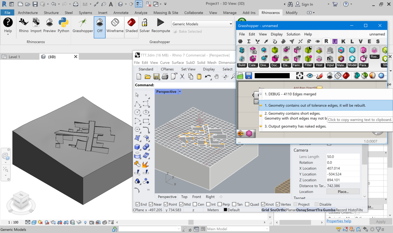
We have released a new build that should be able to fix your out of tolerance edges. It basically explode the polysurface, rebuild the edges to a tolerance Revit can manage and try to join again. The resulting geometry may have naked edges since some surfaces do not touch each other using Revit tolerance. When this happens the component should warn you like in the screenshot.