I got into a point that I feel I’m kinda stuck and would like to hear your suggestions. I have this surface that I want to use it and make it a rood assembly with beams and tongue and groove panels.
I’m planning to use 200mm (8") with 15mm (1/2") gap panels and this being 45 degree rotated to main surface.
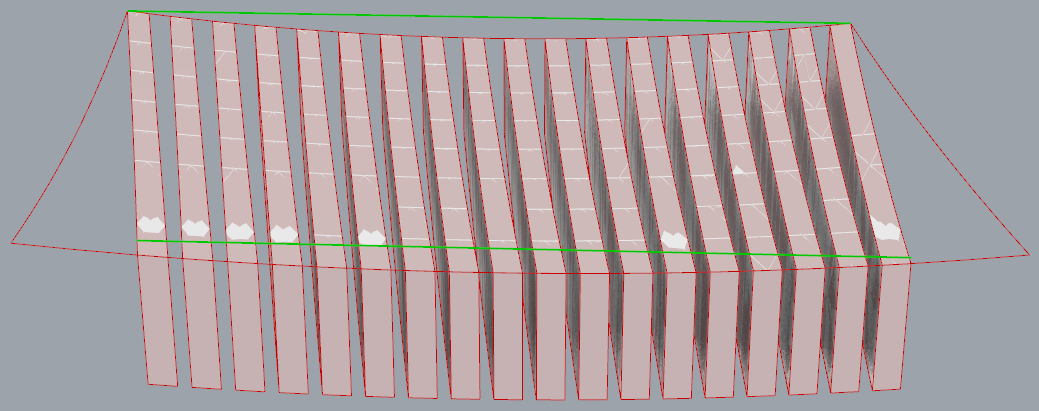
I was able to split the surface but wasn’t able to select ‘one other’ so I can give thickness to panels. I know there could be ten other ways to do it the way I chose was; scale the surface edges, rotate it, dash pattern it with panel width and gap, project it on to surface since it’s double curved, and split it… Once I have the panels I would like to give some radius to chamfer the edges… Pink group in GH is for these panels.
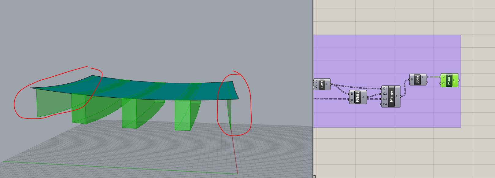
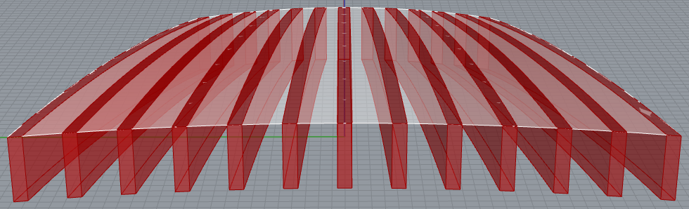
Second, issue that I’m having is for the beams (purple group in GH) both ends are not being solid pieces, I think it’s due to how I divided curves but it would be great to have both beams under the surface.
Hi Joseph, thank you for looking at it. Seems like I had to use True and False on the cull pattern.
Regarding the beams, yes those numbers are just there to test it. They won’t be like this big. I’ve tried to sketch it. Beam edges to be flush with the roof edge and have equal space between them.
P.S. Oops, I just realized I made the beam tops flat instead of matching the surface.
On reflection, lofting the edges to get the top surface of the beams matches the original surface quite well.
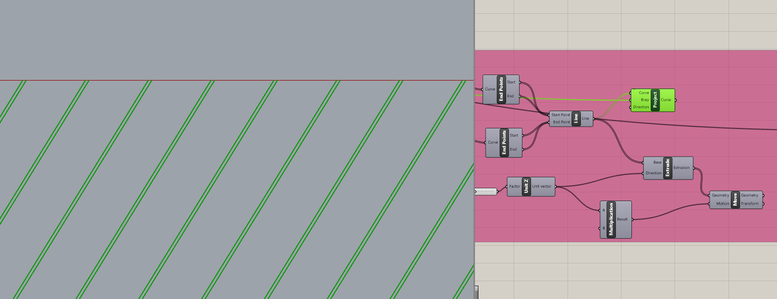
It would be more interesting if your roof surface were parametric. Specifically, I thought the algorithm would work when the front and back are different widths… So as a quick hack, I added this cyan group that scales one of the two lines:
In the process, I discovered an error. Instead of Evaluate Curve, I should have used Evaluate Length, so I changed that. Projecting these lines onto your unscaled surface gives some very interesting results.
This is cool as well. Especially when scale factor is greater than 1…
I agree, it would have been more interesting to have the surface parametric. After your post I’ve tried to make it but couldn’t figure it out. Instead I did it in Rhino so if you want to spare some time, sure.
I’ve got 4 arches with end points and radius. I wasn’t able to create the coordinate system to find points and make the arches. If the height, 2550mm, could be parametric it would make sense thus it can be steep or not…
Too bad, I don’t think it’s very difficult - four points with curves between them - but I’m not going to write it and am not interested in using more Rhino geometry. Enjoy.
I couldn’t help myself… Parametric roof is in cyan group. ‘Sag’ slider (blue group) allows both negative and positive values. Unfortunately, this broke my beam code so I had to repair that. It also broke your code that creates the diagonal panels so I deleted that part (sorry).
I broke it so I fixed it, a little different than how you did it but I used some of your code.
I added a ‘Nudge’ slider (orange group) to move the diagonal lines left or right (±Y direction) to avoid tiny fragments at the corners. Note the very slow SplitMul component (red group) that you might want to disable until all other parameters are set.
Thank you for spending time and repairing the broken codes. I like the way you added the "nudge’ slider to avoid tiny pieces.
I could use your code to make my curves for my surface. I see that you’ve found the mid point of the curve and moved it in ‘Z’ to make it arch. The reason I said I wasn’t able to build it was my arches has a radius ( Start - End - Radius ) and it’s somehow pain in the butt to code it… If I figure it out I will share it with you.
On further reflection, I was right the first time; the tops of the beams should match the roof shape and lofting edges won’t do that.
There are several errors in the code I posted. I’m looking at it again now, will post more later.
As to moving mid points, I made a change so the Z values for each edge are a fraction (-0.1 to +0.1) of the distance between corner points. Subtle but more appropriate, I think.
It’s easy to replace those edge curves with 3-point arcs, eh? Yeah, very slight difference:
The reason I lofted the beam edges to get their top surfaces is because when I used SrfSplit with the projected edges, the fragments were out of sequence (as usual) and I didn’t want to bother sorting them to cull the ones that would become the tops of the beams.
I noticed exactly the same problem creating the diagonal panels so used SplitMul as you did, which in this case at least, leaves the fragments in their original sequence, easy to cull. I don’t know if that is reliable but when I applied the same technique to get the beam tops, it works!
Another significant change I made this morning is that I didn’t bother projecting the cutting curves onto the surface before extruding them to become “cutters” for SplitMul. There is no logical reason to do that and performance appears to be better when I don’t.
Other changes made in this version:
The ‘Sag’ slider now goes from -0.1 to +0.1 and is multiplied by the distance between corner points.
Arc 3Pt is now used for the roof edges instead of IntCrv.
A bug was fixed in the dark purple group ‘Find front and back edges’.
Added a Data Dam component with 10 second delay in front of SplitMul for the diagonal panels (red group), though it isn’t as slow now as it was.
Not sure what else… Two subtle errors remain that I know of:
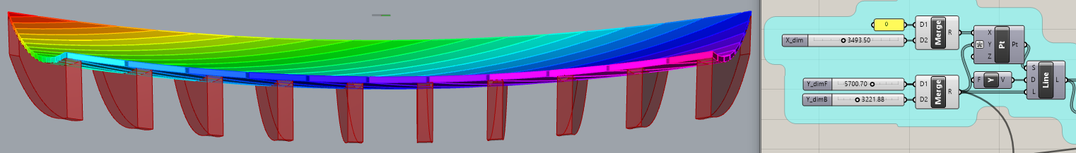
Beam thickness will vary slightly when the beams are not perpendicular to the straight lines where the measurements are laid out. But this feature wasn’t part of your model anyway, so will be fine when ‘Y_dimF’ (front) and ‘Y_dimB’ (back) are the same.
Those two subtle errors you mentioned are OK to ignore cause as you pointed out they were not the aim of my original model but again, having >1 scale factor looks neat! who knows maybe for someone else it helps.
Arc 3pt still not the way I would use. I was looking for 2 points which you have already but for the arch I wanted to give a radius instead of mid point going up or down. But that being said, all four edges of the curve needs to be done same way to build the surface. So I’m not sure if GH is more ‘efficient/faster’ rather than the rhino itself for this case…
Another thing I saw that, you also kept extruding the surfaces instead of offsetting them. Not sure if you have just continued my first code or not but that’s the way it should be, at least for my case. Offsetting make it ‘thicker’ on elevation, since the shape is parabolic. That’s not something I need.
The inaccuracies are not limited to the isosceles trapezoid feature. Projecting vertical cuts on the double curved surface to separate the diagonal planks (“panels”) is not the same as laying down boards side by side, whose edges would be “normal” to the surface.
Obviously I disagree. This roof shape is perfect for Grasshopper. An arc is an arc, whether it’s created using 3 points or two points and a radius. I don’t understand your fixation about radius? You can just as easily modify the distance I move the mid points as calculating radii.
I don’t quite understand this part? But extruding the diagonal planks to get thickness is a distortion of reality compared to laying down boards, whose top surface is effectively offset from their bottoms.
P.S. Please look at this review of 8th grade geometry.
How to determine the mid-point for a 3-point arc using radius.
Offset and Extrude (same as Move) are not the same. Extrude/Move of curves or curved surfaces will result in them being slightly thinner at the ends than in the middle, where they are flat. The offset value is 0.5 but the “Thickness” at the end is 0.474403.
Almost a month ago you helped me on this, it is working just fine.
I was trying to taper the beams as sketched below. 1) I want to offset it from the roof edge like X 2) keep it simple extrusion like A 3) taper it like B. I have attempt multiple times to make it but couldn’t solve it. If you have time, could you take a look ? Thanks.