I think at best, approximately, because at no point is the spiral planar.You can do it in a succession of small arcs but you’ll always have curvature discontinuities at the joins.
Thank you. The thing is that I need spiral arcs for CNC path conaidering cylider milling, I am wondering what would be the best approximation with the smallest amount of arcs?
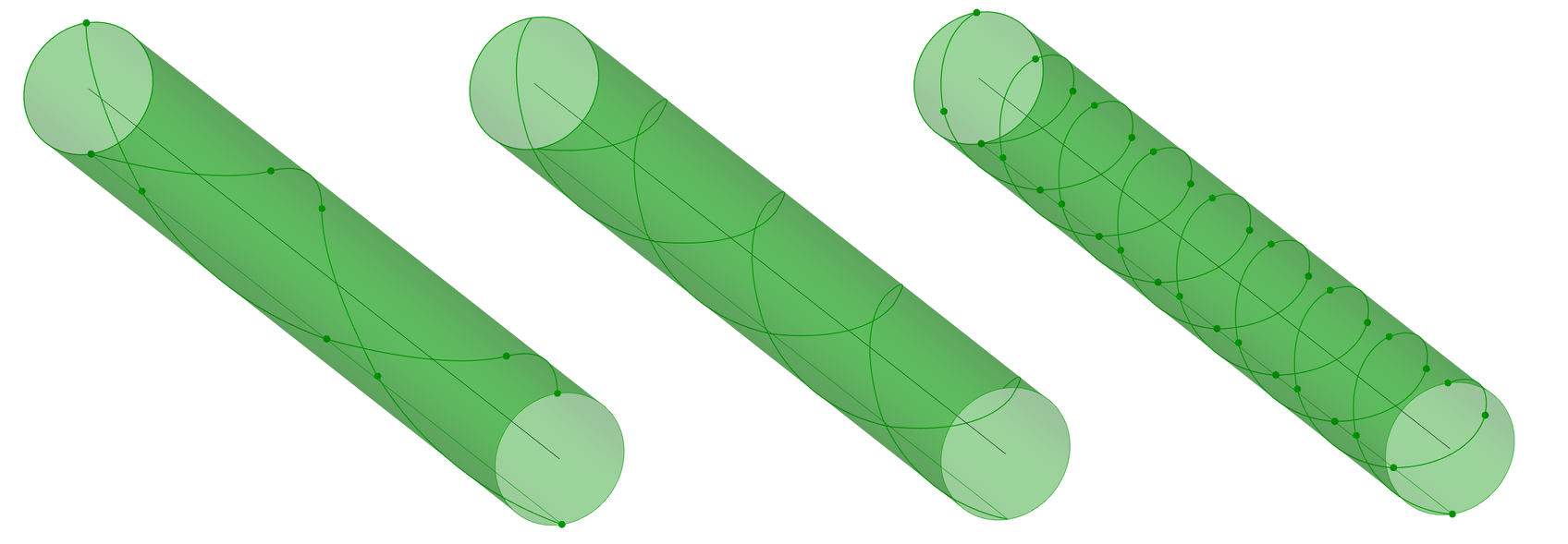
I guess, the more arcs the better. It probably depends on what you’re looking to optimize, and the accuracy of your machining. I calculated the relative deviation from circularity for one turn, for a set of arcs. Even for 4 arcs, the deviation is about .5%.
Back in the late eighties I did conical threads on rock drill rods (starting from 12") on a milling CNC machine using an old Heidenhain TNC-150 control system. I had the CNC to calculate “point-to-point” straight movements using math formulas in a huge loop calculating the next point (ever shrinking radius as the machine rotated around the threads of the drilling bar). The “resolution” of the small steps was parametric as well as the radius of the tool, and so I could control the feed-rate & cutting depth per tooth. I recall using ~0.1 mm straight lines for each step.
In those days there were no arcs in the TNC-150 CNC system (at least not to my knowledge). Anyway, even with the slow CPU’s of 1988 (the machine was several years old at the time) it worked very well.
I used this CNC program for repairing worn out threads on 12" rock drill rods for a copper mine in the Northern Sweden (AITIK). We welded the old threads and then milled them anew. I don’t remember how long the rods were but they were well over 20 feet, I think closer to 30 feet. heavy duty stuff.
I was trying to use this method as well.
I really had hard time to understand the correct tolerance values, because the spiral was always converted to the same curve.
//Arcs = spiral.ToArcsAndLines(0.01, 0.01, 0, 0);