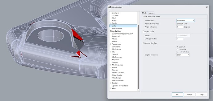
For the type of model you are working in there is nothing that is easier and quicker than true fillets, but your real problem is a terribly messed up STEP import.
First of all just by looking at the fillets in your picture I can tell that was not modeled in solidworks. Solidworks makes fillets that are almost identical to the fillets made by Rhino’s FilletSrf command.
My guess is that this was modeled in Catia or ProE and imported into swx. That is where many of the errors may have been introduced and then more errors were introduced with the swx STEP translation to Rhino.
Your best bet would be to get a STEP file created by the original program where the model came from.
If that is not possible then I would change the tolerance in the STEP file that came from swx. To do that open the file in a program that has a search and replace function like Wordpad. Search for the word “uncertainty”. You should find at least one line that looks like this:
UNCERTAINTY_MEASURE_WITH_UNIT (LENGTH_MEASURE( 1.000000000000000082E-05 )
Since the file looks like its in Millimeters you want to change that to
UNCERTAINTY_MEASURE_WITH_UNIT (LENGTH_MEASURE( 2.54E-03 )
There may be more than one such line. Replace all instances and the save the file with a new name. Then import the file into Rhino8 and see if a lot of the errors go away.
Also, in Rhino you should set the units and tolerance to match (.0025 mm) and then import the file into Rhino. Do not check the join box in the STEP import dialog box.
After the file is imported into Rhino and you have just loose surfaces, you can select all and try to Join the model. If it joins correctly you are done.
If you have naked edges after the Join attempt, then run the DupBorder command and copy those curves to the clipboard. Then undo back to before you ran the Join command and paste in the curves that you copied.
Now you can go around the model where the curves are and fix the errors. You may be able to easily replace defective fillets with FilletSrf if you use the exact same radius.
You may want to make the curves that mark where the bad edges are a distinctive color and make them display thicker so that they’re easy to spot and find.
Don’t join any surface until after the surfaces and edges are fixed. Joining surfaces with defective edges may cause neighboring edges to go bad.
Edit: If in the process of untrimming and retrimming surfaces to fix them you find that the edges are farther away from the surface than the .0025 mm that you set in the uncertainty line of the file, you may want to start over and set the tolerance even looser. Pull curves to surface and use CrvDeviation to determine how far the edges are from surface.
Change tolerance to maybe this:
UNCERTAINTY_MEASURE_WITH_UNIT (LENGTH_MEASURE( 1.0E-02 )


