Hi, I am new to Grasshopper and Karamba and would like to statically analyze a segmented timber shell of this type (see link:https://www.icd.uni-stuttgart.de/projects/segmented-timber-shell/ ). Therefore I designed the planar wood segments on the shell surface. I am unsure about the following aspects:
Do I have to use these single panels as “beam elements”?
And how can I define line supports under the three sides up?
And does anyone have an idea how I can attach the finger-joints?
Thank you both very much! Then again directly to @karamba3d:
This is now the current status. I still have problems with the following:
1.) As a line support, I simply added many point supports, that should correspond to that, right?
2.) How can I attach the finger joints? Should this be modeled by other plugins like “Timber Plate Structures” and will it be recognized by static calculations in Karamba? Or do the individual wood segments have to be somehow “beamed” in order to use the joints from Karamba?
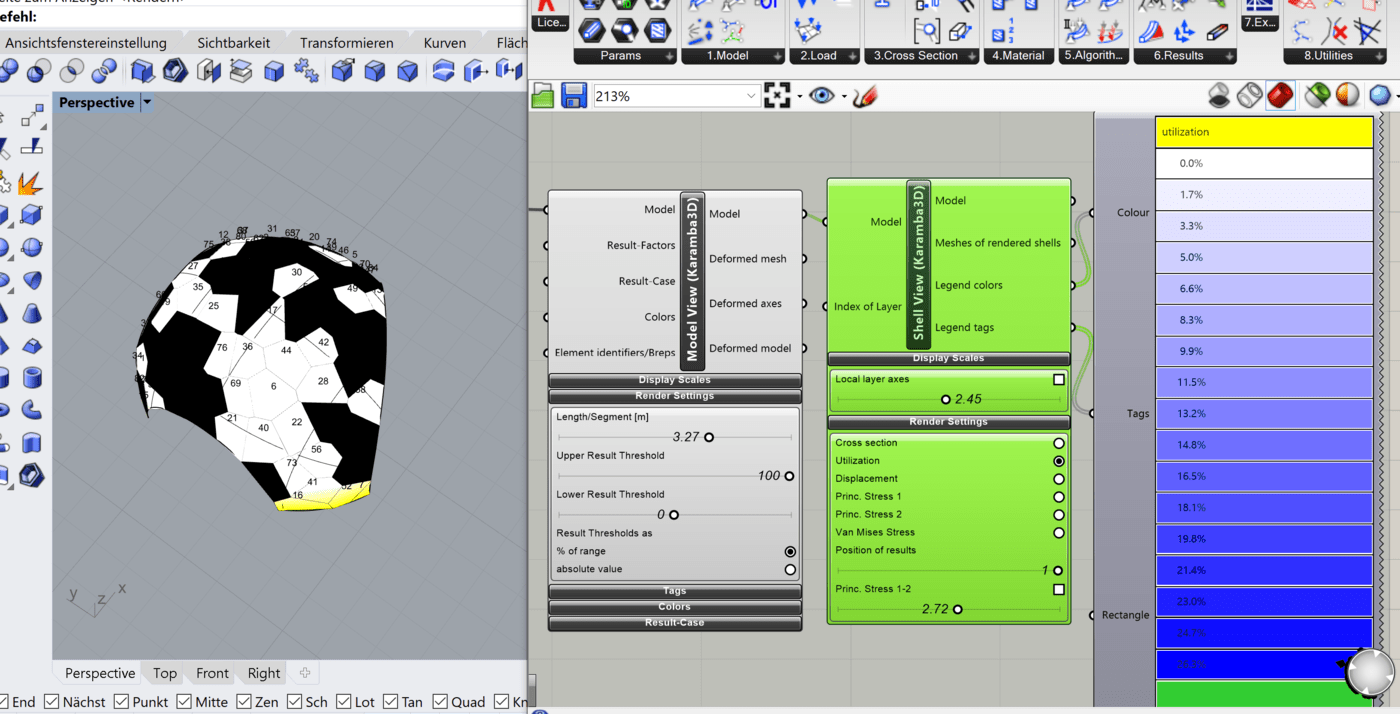
3.) If I want to output the utilization at “shell view” my program crashes every time. Can you see the reason behind it?
4.) And finally, which “analyze” component would you recommend for this shell?
i cannot seem to run your script as it gives an error at the Brep. Can you somehow bake the breps and reference them in the file so that it doesnt rely on other plugins.
By selecting all the points on the mesh at the line would simulate a line support
The joints would not be necessary in the Karamba simulation as your structure acts as a dome and the joints themselves would not play a large role in the overall structure. It would be simpler to keep them in the setup as simple polygons for the analysis, and the finger joints would only be important in the fabrication. Springs or zero length elements can be used to simulate joints between plates if you need to change the stiffness of the connection.
I cannot see what the problem as the script does not work at the moment.
Both analysis can be applied on the structure to see how it performs. You can refer to the Manual on how the analyse components operate.
One thing to not is that you have 2 materials defined, so the material in the Assemble model will override the material in the cross section.
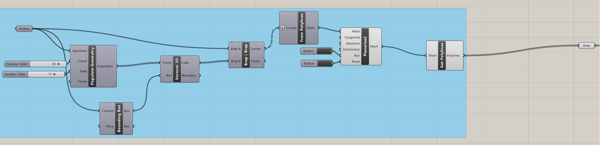
Unfortunately, I have not yet managed to set it up so that everything works as soon as you open it. For it to work, the “Planarize2” component has to run briefly by holding down the “Run” button until all segments are planar (this works fastest if the following “Get Polylines” is separated from the “Brep”). Also, I had unfortunately changed the number slider “count” of the “PopulateGeometry” component at the very beginning from 85 to 80, so my supports don’t fit anymore, so here are the files again: SegmentedTimberShellMONTAG.gh (63.0 KB) SegmentedTimberShellMONTAG.3dm (1.4 MB)
to 1). Which components can I use to do this?
to 2.) How can I put springs or zero length elements on the individual plates?
Is it better in this file with the material?
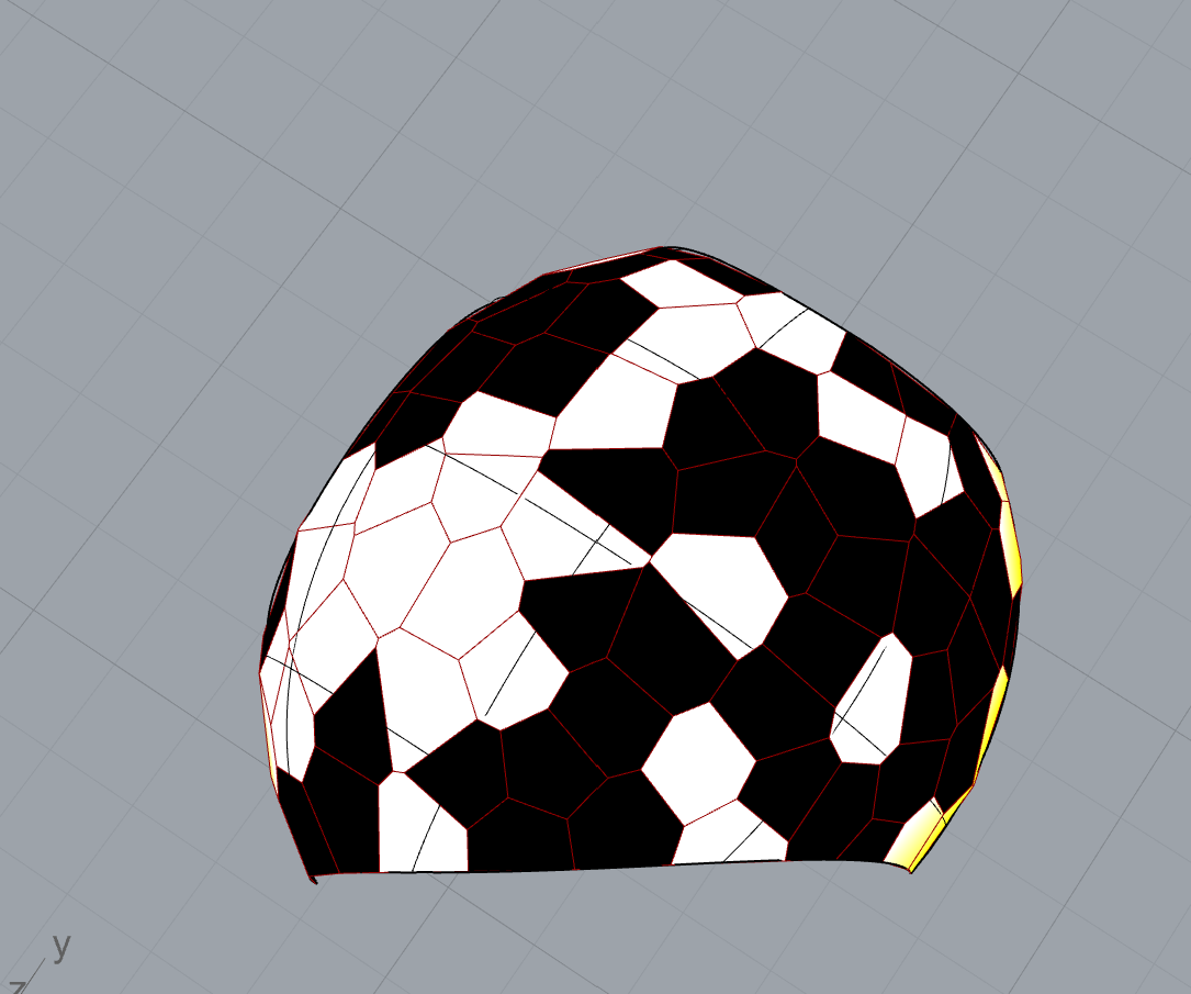
Especially when reopening the file again, black and white colour representations can be seen again, what can be the reason for this?
Hi @sarah.schueller,
I still cannot open your file. Can you bake your breps into your Rhino file and just reference directly from there?
In the installation folder of Karamba, you will find an example that shows hinges between shells, but as mentioned, this step is most likely not necessary for the simulation of the structure. Shell_LinearHinge.gh (40.2 KB)
If instead you use Kangaroo’s Zombie solver, you can get the planarized polygons directly without having to press any buttons: ZombiePlanarizePolygons.gh (92.9 KB)
Not sure I follow - it is giving planar polygons as output like before, just without having to manually iterate.
If you mean you want to keep the base points on the ground plane, then you can add anchors for this like so: ZombiePlanarizePolygons2.gh (96 KB)
@DanielPiker Yes, that’s what I meant, thank you so much!
Do you also have an idea how to define the entire line of the shell standing on the floor so that it can be used as a line support (or many points on these lines as an approximation)?
At @matttam, with the help of Daniel Piker, this file should now be safe to open. SegmentedTimberShellDIENSTAG.3dm (1.5 MB) SegmentedTimberShellDIENSTAG.gh (165.8 KB)
My program still crashes when I try to view the utilization do you have any idea why? And most of the time the shell is colored black and white like in the picture above.
@DanielPiker Oh, but if you now change the Number Slider “Count” of “Populate Geometry”, the information from the “Shell View” will be projected onto the plane and not onto the shell, depending on the number you set…do you have an idea how to change this?
Starting with the Voronoi of the semi-random point distribution you get directly from Populate Geometry like you are, then it is likely that some seeds will result in awkwardly shaped cells, with some very short edges. As the points have to move slightly during planarization this can cause problems. Very short edges could also make things tricky later for fabrication.
Much better to ensure the points are well distributed first.
Here’s an example of pushing them apart, compared with just the raw ‘Populate Geometry’ output:
ZombiePlanarizePolygons3.gh (98.0 KB)
It’s possible some seeds will still lead to bad results - just try changing the slider for the seed of the populate component.
There’s also more advanced optimisation you could do to improve the edge lengths further, but this should help for a start.
@matttam
I’m sorry for the many questions, but I have another one besides, namely concerning the material: The shell is made of beech plywood. When I use “Material Selection” to specify the material properties for orthotropic material, I am asked for some values that are not quite clear to me despite the Manual. For example, how do in-plane shear modulus and transverse shear modulus differ? And what do I specify for wood in yield strength; the bending strength?
@sarah.schueller,
since plywood shows different behavior in the axial direction of the wood elements and in the transverse direction there is also different shear stiffness to be taken account of. However the shear stiffness normally has a small influence on the structural response as long as he plates are relatively slender.
At the moment it is possible in karamba3D (version 1.3.3.) to specify one shell thickness ‘t’. If you want to have different axial stiffness in two directions you need to chose E1 and E2 such that E1 x ‘t’ and E2 x ‘t’ resembles that of the type of plywood you want to use. Since there are three parameters to chose (E1, E2, t) you can also make the mean value of the bending stiffness (E x I) equal to that of the plywood as well.
In Karamba3D 2.0.0 (see here) one can set different strength values for tension and compression such that they correspond to that of your plywood.
– Clemens