Section Lineweights - Successful Workflows and Existing Problems

Hi All,

After tripping on this for a week or so, I thought I’d check in with everyone else on this.

Does anyone have a successful and efficient workflow for setting lineweights to sectioned VA objects?

The two methods I know of don’t appear to be working at all and are the following:

VAobject Section Style → By Layer → By Rhino Layer Dialog

VA Section Style by Layer (Great!)

If you direct a VA object to set it’s section style by the layer the object sits on, the hatch pattern will work with some consistency, but section line weights will not.

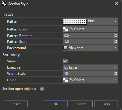
Additonally, withing the R8 section style dialog, you can set the lineweight as a “Scale” or as a “Linetype”, which allows you to target a set of a user created linetype from the properties window.

This would be ideal, as it would mean standards across types would be more easily matched and there’d be less fumbling in VAObject menus trying to remember which object you need to modify. You can just go to your layers or to your linetypes and keep it all organized there.

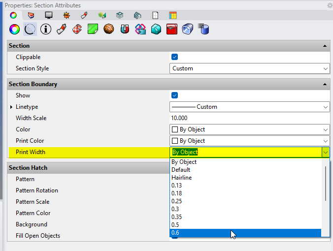
VAObject Section Style → Custom

This allows you to directly set an objects section style via custom properties per object or object layer. More cumbersome to operate since you have to jump between objects to control them, but still workable (if it worked). For example, if I have a concrete slab and a concrete wall, and I want their section properties to match because they should both be recognizably the same material type, I’d rather do that from one location.

Here’s the catch: as far as I can tell, none of these methods work. I have been unable to successfully change the lineweight of a sectioned object (and then print that lineweight) by any method.

Am I missing something here, or is this feature simply not working?

Hi @Clayton_Muhleman the Rhino 8 Section styles dialog doesn’t have the property for a boundary print width. There’s a scale attribute and linetype thickness for the section boundary, that could be used for that, but it currently works for display only, and doesn’t apply to printing results. It’s a pity, but it makes kind of useless to assign the section styles of VisualARQ objects “By Layer”, which would be the most convenient and desired way, because you have no control of the boundary print width.

However, I think this has been improved in Rhino 8 SR14. (I have not tried it yet). Check this out: https://mcneel.myjetbrains.com/youtrack/issue/RH-80568

In the meantime, as you well know, in VisualARQ 3 we have integrated the Rhino section styles into our dialogs, and have added a Print Width attribute to have control of that missing attribute in Rhino8.
You can find it in the VisualARQ styles dialog:

And also in the Properties panel (Section Attributes):

Yes, custom section in VA seems to be the best way to do it. Unfortunately, every

Some print output troubleshooting. Here’s print preview in layout view, which is (except for the undesired green outline on the cabinetry) pretty much what we’re looking for.

Here’s what it looks like in the print dialog and what it plots as. The hatches pick up section boundaries, the cabinets display correctly, and the guide curves magically reappear.

Ideally print preview would be a “what you see is what you get” situation. Any idea how we can get control of these settings?

1 Like

Hi @Clayton_Muhleman can you share a sample file to test this printing issues?

Hi @Clayton_Muhleman got your file thanks! It looks like VisualARQ is not taking into account the “show” status of the section boundary of the slab. I’ll let you know when we fix this.

Glad to hear you were able to replicate the bug!

Looks like I somehow deleted my response above, but to summarize:

It seems like VA has done everything that can be done, due to the parallel functions of the Rhino and VA section boundary capabilities. While VA’s section lineweight is working, the more efficient workflow would be to use layers, which depends on Rhino sections.

I’ll start talking with the Rhino guys to see if we can get this fixed, @fsalla, do you have any insights on when we can expect it to get addressed directly in R8?

Thanks again for your help.

Hi @Clayton_Muhleman I’m also awaiting for McNeel to add a “Print Width” attribute in their section styles. You can follow this request here: https://mcneel.myjetbrains.com/youtrack/issue/RH-81795/Section-Style-Boundary-Not-Using-Widths

Exciting news, we’ve got a new test release that makes the R8 section boundary lineweights work for printed drawings. However it doesn’t seem to work with VA display modes.

The layout on the top is set to Hidden and the bottom is set to Wireframe.

This is with Rhino 8 SR15 2025-1-7 (Rhino 8, 8.15.25007.17001

We’re getting close! Any idea what might be going on here?

Thanks again

Hi @Clayton_Muhleman It’s not working on my side… and I think McNeel has not implemented this feature yet, unfortunately.

I’m trying this with Rhino (8.15.25007.13001, 2025-01-07)… using different display modes (Wireframe, Technical, Shaded…) and printing to raster or vector output. No success!

In my test, I have two curves, the straight one has a print width of “hairline”, the other one a Print Width of 1mm, (just to compare).

Then I have a cone, that has as section style a boundary with a “Width Scale” set to 1, and the linetype has a Width of 1 millimeter.

I’m sectioning the cone with a Clipping plane. So VisualARQ is not being involved at all here.

There is no way to make the sectioned boundary of the cone be printed with the same width (1mm) as the second curve.


Print Width Test.3dm (4.6 MB)

Are you sure? I’d like to see it.

Probably because VisualARQ display modes don’t find any true Print width attribute within the section styles attributes.

I think I may have found the issue. Here it is working in a screen cap from layout view with the monochrome display mode.

I think your file wasn’t working because the “width scale” for the object is set to 1. Width scale is a multiplier, not an actual print width, so any multiple will just be the same line width.

In the screencap above, I set the thin line at 0.1 and the thick line at 1. Then I set the print width for the polysrf at 0.1 and set the “width scale” to 10, so it will print at 1mm, like the thicker crv.

It has some workflow issues, like the section curve scales to view zoom, and we have to use this “multiplier” method of setting the section line weight, which is a strange choice to be sure, but one that at least appears to demonstrate the technical capability of the software to accomplish the task we’re pursuing.

However, none of this works in any of the VA display modes. Oddly, the hatch doesn’t appear to be working either.

Here’s a working example file. Any thoughts?

section lw.3dm (4.6 MB)

Hi Clayton, that’s interesting…
But I’m still confused (we are exchanging our roles here :laughing:.)

Are you saying the “Width Scale” section style boundary is a multiplier of the Print Width of that object?

I guess this means it is not possible to assign a “Hairline” to that object, and get a “predictable” print width to the section boundary of that object because “Hairline” thicknesses can’t be scaled, am I wrong?

Your example seems to work when the Linetype (in the secion boundary) is set to “By Layer”. But it gets out of control as soon as you select a “Custom” linetype. I wonder what is the relation with the “Custom Linetype” Width value (also set to mm).

@stevebaer can you shed some light on how this works?

We will fix this as soon as we have a clear idea of how line widths in section styles are currently working in Rhino.

This one’s going on my highlight reel, for sure!

Yes, that’s how it appears to work, at least. Which is why your file wasn’t acting as expected. With the “width scale” set to 1 there’s nothing to multiply.

Good question about hairline. Just tested below, it looks like hairline does have an actual value that’s capable of being multiplied.

One additional note, it seems like the rendering method for print preview of these section lines scales to the viewport and not to any actual “print width” unless you’re in an actual print dialog. Then it will scale accurately to be the multiple of the projection line weight. Not ideal, but working where it counts.

Also curious about this, because it could be a useful workflow for architecture where actual line weights are controlled in a separate register, outside of byLayer or byObject. Not unlike AudoCAD CTB files, but way better.

I initially thought this was the intended workflow and spent way more time than I should’ve setting up a file to operate this way before I realized it wasn’t working yet.

Glad to hear it, and I’m sure there might be some useful insights from the VA team to the Rhino team regarding how Rhino section line weights could support architectural workflows. Thanks again!

1 Like

hello there,
I just delved into this issue as well and thought I’d ask if something improved?

atm I can not find a solution on changing boundary-lineweights other than per object (custom section style).
I tried to set the section style to parent to make my life a little bit easier but the changes only work on the lowest level of a group / block. (parent is not working)

In addition I wanted to ask if you could add an option to the va-section-style / va-plan-view-styles that allows for an view override (custom) but also lets you change lineweights per object.

Ill explain: right now when I want ALL cut elements to display a solid hatch with whatever color I chose AND change lineweights per object base (only possibility right now - correct me if I am worng) I have to alter the section style in the layers and then alter the object at its lowest level to a different boundary line weight.

the other route which is not working atm would be to make an override in the va-section-style and click a box that lets alter the lineweights per object later on which is not working - this would be a cleaner method I think because with the approach right now, I need to alter every new layers section style…

best regards,
sebowim

Hi @Sebastian_Wimmer

This is the current status of VisualARQ and Rhino Section Styles regarding the section boundary line-weight:

  • Rhino and VisualARQ objects take the section boundary “line-weight” according to the “Width Scale” value, which is a multiplier of the “Print width” value assigned to the object or to the layer.
  • If the layer or the object has a print width set to “Hairline” it is not possible to control the final section boundary print width, unless you assign it from the VisualARQ Section Attributes section, in the Rhino properties panel:

  • But this attribute is not available in the Section styles dialog by object or by Layer.
  • The Rhino section styles are not printed correctly (right now) on VisualARQ objects when they are sectioned by a Clipping plane. They work with VisualARQ Level cut planes and VisualARQ section lines though.
  • The section styles assignment set to VisualARQ “by Parent” inside blocks, doesnt’ work well, as you reported. We will revise this as well.

The section Print Width attribute is currently missing in the Plan/Section View Sytles Overrides. We can implement it, including the “by Object” option.

@Sebastian_Wimmer this has been fixed in VisualARQ 3.3. You can download the latest RC here: -3-version-3-3-rc3-released/201601

1 Like

@Sebastian_Wimmer we have added the Print Width attribute for plan and section view Overrides in VisualARQ 3.4 RC1: VisualARQ 3 - Version 3.4 RC1 released

1 Like

good morning @fsalla, I went through the changes very quickly and can confirm, that the print-width override works, at least in this very fast test.

BUT, there are some things that I don’t get: (they might have not worked before)

1)I normally use the PEN displaymode because I had bad experiences with output of pdf-printed HIDDEN details, lines were off, circles evolved to crazy uneven polygons etc. so I never got to experience the vaExporToDWG (why does it only work with HIDDEN and WIREFRAME, when PEN and TECHNICAL also print as vector?)

but I tried it now and maybe I am doing something wrong, but it is quite off;

  • it does not export any geometry or annotation ON the layout
  • dimensions are exploded into text, lines and hatches
  • when you have more than one detail it spreads them out horizontally and not keeping the layout

2)why does the section marker show through the geometry when using PEN?

090425_VA3_Test_DWG.3dm (4.6 MB)
090425_VA3_Test_MASTER.3dm (4.6 MB)
L1_PEN.pdf (27.1 KB)
L1_HIDDEN.pdf (26.9 KB)
L2_PEN.pdf (27.1 KB)
L2_HIDDEN.pdf (26.9 KB)

3)could you integrate a region for section-views as you have in the plan-views?
this way not everything in model space gets cut on one side, which leads to turning sections on and off a lot.

best regards,
sebowim

Hi @Sebastian_Wimmer

  1. The Pen and Technical are Rhino display modes that have some features that are missing in VisualARQ Hidden display (like the ability to show the hidden lines). The code to export to DWG doesn’t support that feature (yet), and for that reason we haven’t implemented the DWG export with these display modes, or they don’t work as expected. So until this is not implemented, it is necessary to use the Hidden (or the Wireframe) display modes to export to DWG.
    On the other hand, I’m interested to know more about your bad experiences printing to vector with the Hidden display mode. Please send your cases to visualarq@asuni.com (or open new posts here) to report them so we can improve the vector output results.
  2. Do you mean in the exported DWG? when you export a detail in other display modes that are not Hidden or Wireframe, the views are exported as a raster image to ensure you see the same as in the page layout detail.
  3. Do you mean in 2D Section views? Yes, we can consider this feature for future versions. But if you use real-time section views of the model you can control that with the Detail frame.

hi @fsalla,

  1. alright I understand your points - when I have time I can look into older projects to find some examples, or maybe now I start using the displaymode and find problems or hopefully not.

(+) BUT more important would be the bullet-points, is vaExportToDWG working for you? Because on my end I have the problems I stated:

  • it does not export any geometry or annotation ON the layout (only the detail-view)
  • dimensions are exploded into text, lines and hatches
  • when you have more than one detail it spreads them out horizontally and not keeping the layout

I would be interested in how you are using this feature in it’s current state? Because for me it does not work or does the stuff I would need.
Maybe a tutorial video or written, would be good.

Sorry I missed to upload the DWG-FILES:
L1_HIDDEN_DWG1.dwg (1.5 MB)
L2_HIDDEN_DWG1.dwg (1.5 MB)

in the 090425_VA3_Test_DWG from the last post you see the DWGs imported back into rhino

  1. in the pdf L1_HIDDEN vs. L1_PEN to the left

  2. yes, like you choose a region of what you want in plan-views, to choose a region on what to want to get cut in section-views - this way you could have numerous section-views active and you model space is still workable because the stuff outside of the region does not vanish

best regards,
sebowim

Hi @Sebastian_Wimmer

I’ll appreciate that, thanks!

This works well for me with your model. Also in your DWG file. The only issue is that the text size of annotations laying in the layout space is not preserved in the exported DWG file. This is something that happens due to a bug in Rhino, which we can’t help it, unfortunately. If you save your model to DWG, you will see that text size of dimensions in page layouts is not preserved either.
I’ve reported this already: https://mcneel.myjetbrains.com/youtrack/issue/RH-86992/Text-size-inside-dimension-is-not-saved-correctly-to-DWG-DXF

This works fine for me. I’ve opened your DWG files, and dimensions come as dimensions.

This is done by design. The 2D inside each layout detail is generated as 1:1 drawing in the model space. If you have more than one detail, each group of 2D drawings is generated with some spearation in the model space. At the same time, a page layout is generated with the same details (pointing the 2D drawings generated in the model space) and annotations you had in the original 3dm page layout. This way you keep the same layout view in the DWG than in the original 3dm.
Do you expect that the whole layout would be created in the DWG Model space? that’s something we are considering to do in future versions. But would you assume that this way you would lose the scale of the 2D drawings?