Right Triangle detect

Hello,

I’ve been trying to figure out how can I detect the right triangles that may exist along a shape borders (curve). My input comes as 2D polylines and my goal is to get an regular shape as a left over. I’ve tried look for trigonometry to understand how determine cathetus only getting the hypotenuse and inside angles.

Here an example kind of shape that I can get:

And here my goal:
(Red dash lines are the possible right triangles and Blue ones are the left over shape)

I’ve tried some ways, for example, shifting the vertexes I can get the position of the actual vertex and its back and front vertexes as well, so I can draw a rectangle. Also I can draw a circle from the midpoint of my hypotenuse to the front vertex. After drew the rectangles I test which circle has 4 points incidents, and then culling the outside points from the original shape.

My result was:

Definition:

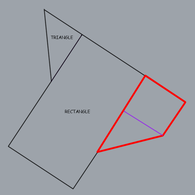
Seems working fine, but actually my real input could be a non orthogonal shape, for example:


(I drew the right triangles manually in red lines).

My definition doesn’t work in this type shape and I can’t figure out how to solve this problem. :frowning:
Note: I work with only one single polyline, not for a set of curves.

Can anyone help me with this tricky mathematical problem? All help is welcome!

Thankyou so much, this forum is great!

Right Triangle detect.3dm (30.2 KB)
Right Triangle detect.gh (23.8 KB)

Follow up definition working with non orthogonal shape:


Result:

(pretty spot on what I’ve been seeking)

But, doesn’t work with a case what I have orthogonal occurency:

If I rotate the shape, the definition works well:

But if I rotate too much, errors comes true:

Again:

Any idea guys??

Right Triangle detect V2.3dm (29.1 KB)
Right Triangle detect V2.gh (8.0 KB)

Welcome @felipe_posa,

Here’s how I would probably approach this:

I. Evaluate the Inital Boundary

Step 1: Explode the Boundary

Explode your boundary polyline into segments.

Step 2: Shoot Rays in Positive Direction

Go through your segments one-by-one and shoot a ray from each segment end point in tangential direction of the segment, to find intersections with other segments of the boundary. Keep only the lines/rays that intersect another segment and lie within the boundary.
For more complex, initial boundaries, it can happen that a ray has multiple intersections, in which case you only want to keep the closest one!

Step 3: Shoot Rays in Negative Direction

Repeat step 2, but this time go through the lines in reverse and shoot straight rays from their start points (instead of the end points).

Step 4: Delete Oblique Rays

Delete rays that don’t intersect the other segment at an angle of 90° (resp. 270°).

Step 5: Subdivide the Initial Boundary


Divide your initial boundary into however many new regions you have found. The goal is here to get new closed boundaries, for this example three.

Step 6: Evaluate the New Boundaries

Go through the new boundaries and check whether they are rectangular or triangular.
Those which are not, need to get processed again, with a similar but a little different approach.

II. Reevaluate All Non-Conforming, New Boundaries

Step 7: Shoot Rays in Positive Direction

For each boundary that needs to be reevaluated (here only one), explode it, go through its segments one-by-one, and shoot a ray from each segment end point in “normal” direction of the segment, to find intersections with other segments of this boundary. Keep only the lines/rays that intersect another segment and lie within the boundary.
Here you need to shoot two rays from each end point: one in normal direction to the right and one in normal direction to the left.
For complex boundaries, it can again happen that a ray has multiple intersections, in which case you only want to keep the closest one!

Step 8: Shoot Rays in Negative Direction

Repeat step 7, but this time go through the lines in reverse and shoot rays from their start points (instead of the end points).

Step 9: Delete Oblique Rays

Again delete rays that don’t intersect the other segment at an angle of 90° (resp. 270°).

Step 10: Subdivide Each Non-Conforming, New Boundaries

Divide each non-conforming, new boundary into however many new regions you have found. The goal is here to get new closed boundaries, for this example 2.

In my opinion, this is a much better approach than using circle intersections.
However, it might be more tricky to implement than you think. Therefore, I’d break it down into subtasks to make more approachable.

4 Likes

Here’s another possibility, which uses a component Manhattan Distance found in the link below. I’m not sure if you’re still required to first become a member of the Milkbox Group to download it - it’s been a while.

non-orthagonal.gh (8.1 KB)

2 Likes

@diff-arch thank you for your explanation! I also thought that I could take a internal rays extend study to solve this question, but how you said it’s seem very tricky. Thank you!

Thank you, great solution!