You can now create Geometric Tolerancing control frames in Rhino 9 WIP.

Interview with the Developer
Geometric Dimensioning and Tolerancing (GD&T) is a system that uses symbols on engineering drawings to define and communicate the acceptable variation in a part’s geometry.
This ensures it will function as designed if manufactured to the specifications detailed by the symbols.
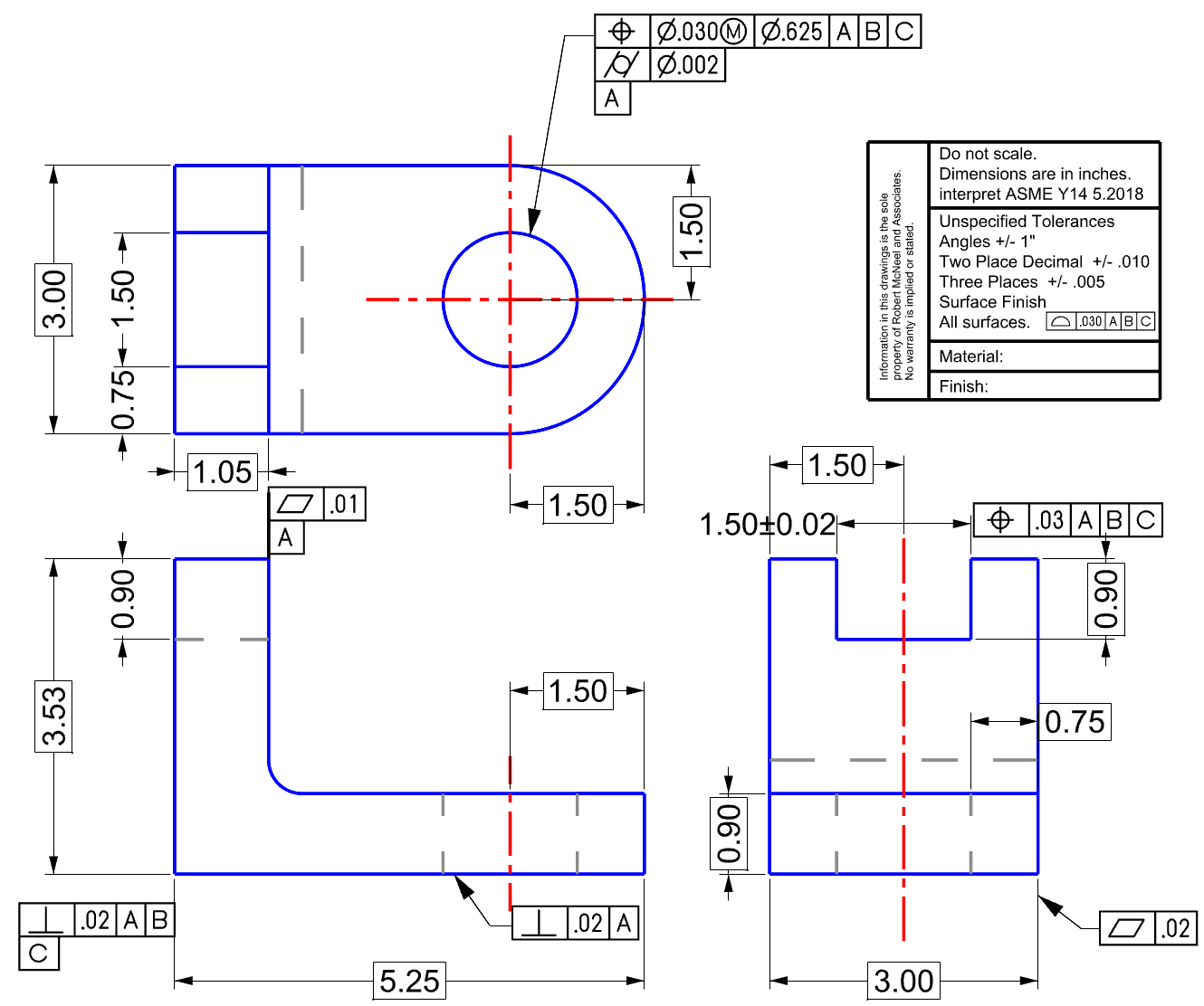
Here is an example of a GD&T Feature Control Frame:

Why?
Users familiar with other applications that have this capability have requested this feature in Rhino.
Those involved in manufacturing will now be able to produce drawings with these GD&T annotations in Rhino 9.
What you need to know:
- The new GeometricTolerance command builds a feature control frame to display the special text.
- The feature control frame is made up of a simple text entity that is assigned to the annotation style Geometric Tolerance.
- The annotation style Geometric Tolerance is configured with a GD&T font that is specifically designed for use in geometric dimensioning & tolerancing. This font is capable of producing a boxed basic frame.
- This font uses metrics to create boxes around characters, align these boxes and build special strings that control the display of the GeometricTolerance.
- The GeometricTolerance object can be edited by double-clicking. The existing text will be displayed in the command dialog for editing. Edit and pick OK. The GeometricTolerance will be updated.
See the geometric tolerance in use here.

Try it:
- Download and open file in the Rhino 9 WIP: GeoTol Try it.3dm (94.6 KB)
- Use the suggested Geometric Tolerance on the light gray Try it layer as a guide to create your own control frame
- Type GeometricTolerance or click the command from the Drafting menu, Other Annotations and GeometricTolerance.
- Fill out the form as suggested. Click OK.
- Pick a location and your Geometric Tolerance Control Frame will appear. (you can move it with the Gumball, if necessary.)
- To edit the Control Frame, double click and it will be added to the Control Frame Editor.
- Click OK when editing is complete.
- From the Layers panel, turn off the Do This layer.


