True if the object is comprised of simple geometric shapes.
Also true if the object has a complex shape but the model only needs to “look like” the object and it is not necessary to capture the shape with any degree of accuracy. Examples are models which will be used only for rendering or in animations or games, or used to create toys or hobby models.
However if the object has a complex shape and the details of that shape are important then starting with scanned data will frequently be quicker and generally result in a more accurate model than using data from hand measuring. Examples are models which will be used to design mating parts, or models for some types of engineering analysis such as CFD.
Even in situations where the accuracy of the final NURBS model is not critical, it may be quicker and simpler to use existing scan data as background in Rhino, than making physical measurements and inputting those measurements into Rhino.
A key in using scanned data is to know how to use it. Sometimes it is possible to go directly from the scanned data to a usable NURBS model. Frequently however it is best to use the scanned data as a background on which to create the NURBS model with the needed level of accuracy similar to what hanscad and I described above. Another key I’ve found to using scanned data in Rhino is to not import it into the same .3dm file as the model I’m creating. Rather I use Worksession and keep the scanned data in separate files from the NURBS models.
I’ll chime in here and note that I essentially RARELY use T-Splines anymore, and almost exclusively use VSR/Autodesk Shape. Shape is actually far more powerful when working with laser scanned data/meshes than people realize, frankly I’m not sure the folks who made it understand how good it is. While it doesn’t have the sort of “shot gun approach” auto-surfacing you’ll see in Geomagic and such, I’ve never found the results of those programs to be acceptable, and when you compare the price of Geomagic or Rapidform ($10k-30k USD) to that of Shape ($1,325) you realize that Shape is an absolute steal. I was lucky in that I exercised the upgrade option from the previous version of Shape, which was only like $300, but I’d still happily pay the full price. I will say that the learning curve for Shape is steeper than you might initially think, as it essentially forces you to think like a Class-A automotive surfacer. In the long run though, this is a good thing.
For instance, this is a canopy I did for a customer recently. The tooling was made up of 3 different pieces that were laser scanned. I assembled the tools together in Rhino, and then used Shape to make the surfaces.
[quote=“hanscad, post:22, topic:24470”]
Also: so that’s what Worksession is for!
[/quote] That’s what I use it for and I find it essential.
But it appears this is not what Worksession was originally intended for. The documentation implies that it was designed so that multiple users could share files for referencing. The Worksession command lets more than one user work on a large project. By breaking the project down into many files, one user can edit a part of the project while another user edits a different file. Only one user can have a file open for editing, but many users can see it.
The associated LimitReferenceModel and PurgeRefObjects look like they could be very useful although I have not tried either.
@Sky: thank you, the canopy looks great! But I don’t have the budget for such a big chunk of software expense again - if I could trade in my T-splines license for Shape I may consider it, but not in addition to T-splines.
I don not really understand the terminology of “Automotive Surface” or “Class A Surface” etc. - I kind of thought it was more like a marketing catchphrase…!?
I work towards tooling for injection moulded model kits, which some here kind of dismissed as not having to be accurate. In a way there is always a certain element of compromise (due to size and material) when designing a model kit, but still, the outer shapes need to be as accurate and closely to the original as possible. A deviation of something like a Millimeter might be acceptable as when scaled down that becomes a fraction of a Millimeter. However, the human eye is able to pick up remarkably small shape deviations (or errors) and in general, today’s model kits are designed for the knowing enthusiast (such as myself), with a certain degree of compromise to not lose the casual buyer/builder due to price.
So in a nutshell: I need to create watertight, defect-free surfaces as close to the original as possible, but with a certain degree of simplification. Surfaces need to be smooth and ripple-free, but whether or not I can call them “Automotive” or “Class A” is of lesser importance I think as perhaps tiny curvature problems may fade to nothing in the target scale.
Cheers
Jeffrey
There are a FEW things that Shape will do that Rhino will not, but more than anything it allows me to work far faster than without it, and with a slight increase in overall surface quality. Really though, you don’t need ANY of those programs to do what you want. You can do everything quite well with Rhino commands for aircraft. Remember that 90% of aircraft surfaces are simple/straight lofts. If you understand where the important cross sections are for any aircraft surface, you can use the Project command (or MeshIntersect using a mesh plane to intersect with the scan data) to extract raw cross section curves. You will need to Rebuild/Simplify/Edit/get creative! with those raw curves, and then loft them. For the most part, aircraft surfaces are quite simple, and all those programs you mention at the top will make a huge mess, in the same way that Geomagic or Rapidform would make a huge mess.
And - use PointDeviation to check the fidelity of your NURBS surface to your original laser scanned data.
And, fwiw, that canopy could have been done with basic Rhino commands. Shape just made it easier. And I suspect that the majority of those reverse engineering software packages would make something worse than what you can make with just using Rhino.
I almost solely work with laser scan data when creating my reverse engineering models. Ships, planes, impellers, etc. What works for me is to first isolate the scan data into sections or layers, however this will be an added service or software expense. If building a ship for example, I will isolate (or separate) the keel from the hull, then work on each separately in Rhino. With a cleaned up area of points, it’s easy to create curves, or apply a patch surface to the points as an excellent starting point. We have examples on youtube. https://www.youtube.com/user/Summit3D
Wow, that is some heavy duty work there in your videos! Both in terms of physical size of the project being a ship and in terms of features (bulkheads, structure, piping, etc.). The scan files must be massive or at least many large scan files.
I think I may have understood this, and if i did, please, forgive me. If I have a mesh to work with, and Rhino can’t "See’ it, I use the “Extract Wireframe” command, and then proceed to pick out all the superfluous junk I don’t need, and am able to make a Mesh of my own. The lies may be not contain enough control points, but I insert them, and slowly smooth out the model. I try and do everything in Rhino, and people have seen stuff they though I did in Photoshop. I have CS3 and CS5, but sometimes it’s just easier to work with what your working with.
I reverse engineered this Mesh and though the Battlestar Stealthstar Viper look the same as others if you look at the meshes, they look completely dissimilar. Thank You
John
You might be interested to try EvoluteTools T.MAP for Rhino for re-topology tasks, which is currently in public beta stage. Our current version already includes quad mesh output, this blog article gives an overview.
We are currently working on improvements for EvoluteTools T.MAP, but using the current version you should already be able to get quad meshes useful as a starting point for T-splines reconstruction. Please post questions and feedback regarding T.MAP in this thread: Release of EvoluteTools T.MAP *beta*
This webinar might also be interesting, among other things it shows how T-Splines and EvoluteTools Lite/PRO can be used in a combined way to fit a T-Spline to reference geometry: https://youtu.be/0e2_NMU_HL4
My settings prevented me from seeing a response was made, I do aplogize for my ignorance. The model I posted above completely unfolds, and can be made (except for the cockpit glass) into a paper model. I do not think this ability exists with T–Splines. It would be nice to know that this does. I see people bang out Renders, like the Buccaneer", but there is not way to “make” that model using mixed media without doing much follow up work. Is T-Splines basically to Bang Out Renders? I don’t know, which is why I ask.
Also, we have made cockpit glass for home-built aircraft, and this kind of accuracy would have been scoffed at, when plywood forms, hand sanded plaster, and vacuum, are being used to form the Lexan. Nice accurate picture, but unless this is for a military aircraft, well, I am ignorance of what the point is. It’s easy enough to convert a Mesh into something you can use for Rhino by first removing the superfluous lines not needed in the mesh, the converting those lines to curves, and start rebuilding the model. As I said, the Picture of the “Stealth Viper”, this is more than a Render, it is a buildable model in whatever scale you wish to build it in. I tend to design parts that I know will work, than go back, and try to tweak a drawing. Designing a part of Rhino is far different than making a nice looking Render. I ask this in all sincereity as I am open, completely, to finding an easier way to do anything. Thank You.
Thanx Steve.
Yeah, I saw this some time back when I started looking into this.
Pretty slick software.
How would it work w/the sheetmetal unibody of a vehicle?
Any ideas?
Dear Sir/Madam
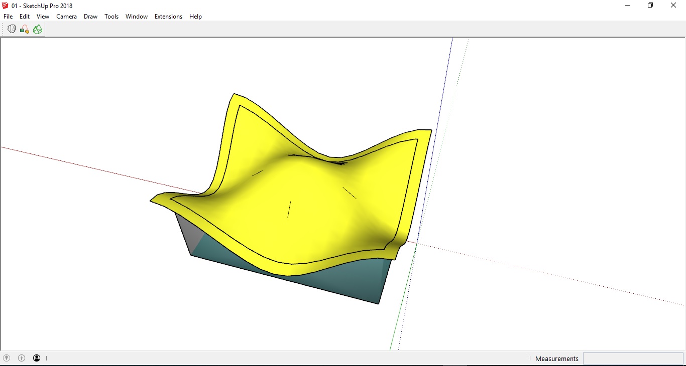
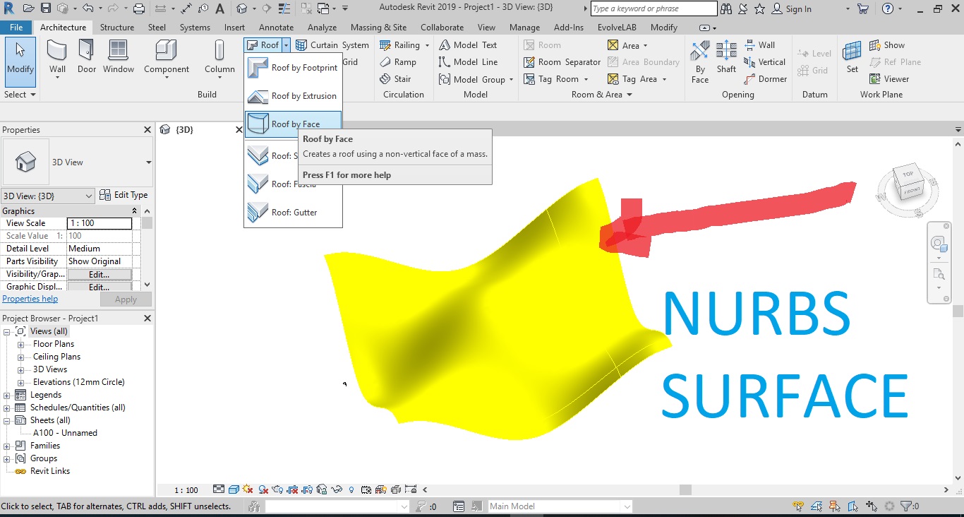
Hello, I reach you in order to kindly ask you, is there any way to export Sketchup to Revit Models when I have a curve form? Meanwhile, EvolveLab’s plugin (For transferring SKP to Revit) best solution only can set up for cubic volumes with straight lines but when we have curvilinear free-forms it cannot handle because as you know SKP interface is based on mesh and Revit or Rhino has NURBS interface. Therefore, when I import SKP file(I have tried to export in different version and solution)(IFC,…) then the roof or wall transform to triangular shape as mesh surface and I cannot use roof or wall toolbar in Revit. Indeed, I wonder to have one shape to make it roof or door in Revit. (Nurbs Surface- attachment file)
Furthermore, I have imported SKP file to the Rhino6 in order to use the Meshtonurb command (Reverse engineering a mesh into a smooth surface) but unfortunately, Rhino still preserves all the original facets so it wouldn’t be too helpful for me. Is there any third party Rhino plugins or solution that make an attempt to smooth the surface (Nurbs) in order to use in Revit?
It would be your kindness if you assist me to export Sketchup to Revit Models when I have a curve form. Thanks in advance.
P.P: I have tested the SharkCAD Pro-AP or ViaCAD 10 software in order to transform my file but unfortunately they automatically transform all mesh surface (Curve form) to Nurbs surface (Even straight lines) and you miss your main idea and also form.
This my phone number: 00393473603328
Email: Khademi.hr@gmail.com