Hello everyone,
Freelance designer here, i have been given a STL mesh to work on and supply a CAD model with some modifications in regards of the original mesh.
I know this can be a tricky subject and while I have done that on some simple models (where you can easily extract geometrical primitives) this one is more on the organic side of things (hand sculpted part to give it a nice look before making the tooling)
Unfortunately right now I can’t share the mesh and before diving into one of the many ways to do this,i would like your input on one of these methods :
A - Extract the global outline of the shape and a few cross sections “as-is” see how the surface creation goes on and modify the base curves until target is met : I may loose some details in this process
B - Segment the mesh by complexity : main issue on using this method is to make sure there is a full surface continuity between each surface reconstruction.
C - Going the SubD route and try to fit a shape to the mesh (how ?) then rework this thing converting to NURBS : Looks like a huge time consuming method for poor result.
D - Find a plugin that can help with extracting features, curves to make sure the key areas are fitted to the mesh. I have heard of Mesh2Surface but before investing is such software, does any one has been using it or used another plugin of this kind ?
I tried the easy way with the aim of getting some “approximate” NURBS surfaces on which i can extract curves and rework them
First thing first, i splitted the mesh in half to get rid of the junky triangles (this is a symetrical part)
I tried using QuadRemesh and found out the result was quite good (Target Quad Count :8000 with 50% adaptive to get all of those details and simplify afterward) see below :
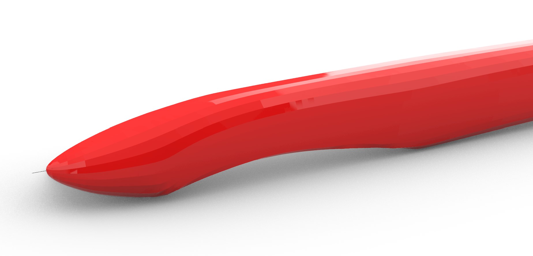
But when converting to NURBS, i end up getting weird surface continuity (red glossy material for the sake of seeing the surface continuity problem). It would take me way to much time to rebuild each curves
Sorry for the long post.
I know each reverse engineering project is different but if anyone has some hints on the way to go or on a method they have used successfully in the past on such thing, your help would be greatly appreciated.
The image of the mesh appears to show a crease/hard edge which is lacking in your model. Is that intentional, or the result of the procedure you have followed?
First, I would consider how the object will be manufactured in the real life. 3d printed parts are easy since they are not restricted by manufacturing specifics such like draft angle, ability of the CNC-milling tools to reach deep areas etc. Injection moulding, on the other hand, usually requires 2 degrees draft angle for each of the pieces to make the extraction easier.
As for the reverse engineering itself, the Mesh2surface plug-in lets you use it for 14 days for free since it has a trial version that you can download from the official website:
It’s fairly easy to use and I already had one project made thanks to the trial version.
Another way is to manually draw curves and use some of the surfacing tools of Rhino, such like: Loft, Sweep 2 rails, Sweep 1 rail, Network surface, Blend surface etc.
You can also may want to start with a deformable NURBS sphere and adjust the position of its control points to make it follow the same shape. Judging by the images you posted above, it looks like the general shape is fairly easy to make. The concave area was made via another surface used to trim the main body.
Lastly, and probably the easiest and fastest way, is to rely on Rhino’s SubD, which is very straightforward to use and its main advantage is the ability to quickly modify the shape according to your liking.
Thank you for your reply and your guidance.
The original part was made in pure CAD and prototyped in some high density urethane board to get the client approval, but it was not accepted as being “too CAD like” despite following the design specs to the letter.
After that the prototyped part was hand shaped to accomodate the need for a more organic shape and then i got the STL file to work on
The hard edge is just an intersection made in the initial volume to create a reference surface to mount additional items on this part. it is a simple Wirecut . The newly created edge would then get a filet after that. The pictures above are just the results of the procedure i have followed.
I will be able to get the hand shaped part and use it as a visual reference to make design choices.
What is the relative importance of reproducing the scanned part versus suitability of the Rhino model for further modification and refinement? More control points can allow a better fit to the scan data but make further modifications and fairing more difficult.
Keep in mind if SubD is used a SubD surface inherently has zero curvature normal to any edges or creases. That can cause problems with matching a shape.
This part will be moulded using composite material such (mainly a mix of different kind of carbon fibers) meaning I have to get a mould out of this shape.
I can surely get along having 0° draft on the joint plane as the part is curvy enough and doesn’t have any perpendicular wall.
Thank you for your comments on using a deformable NURBS as a starting object and pointing to using SubD.
I will give a try to Mesh2Surface but i just want to make sure i start in the right direction without wasting some trial time
I will try to document the process here with the things I can share
Suitability of the model is more important to me.
I have to find balance between a bunch of control points to fit the mesh and the organic shape that I need to reproduce while also taking into account that this was hand shaped tough less than perfect in terms of regularity.
Thanks for your inputs.