Refusing to Accept These SubD Corners Cannot Be Better - Eeep!

I am still somewhat new to SubD. I am working up a car body in SubD, whilst doing CFD in OpenFoam. I would like to keep the body in SubD for as long as I can, before chopping it to pieces, because I don’t have the actual frame and interior worked out to the actual n’th.

This approximation of a NACA duct submerged inlet was drawn from scaled official NACA drawings, so, I want to keep its shape pretty close before beveling it, also for as long as I can in the process, because there’s no way to unbevel it, I think. I think that adding some bevels might alleviate this problem, but I want to keep the accuracy as best as I can–for as long as I can.

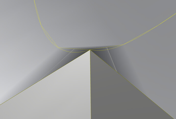
The corners, my corners are crap. I’ve gotten them better by taking the tension out of them, but the very corners themselves, are indeed crap. After a few hours, I have the center line fairly good.

I know I have some triangles in this, and I also know quads would be better, but if anyone has an idea where my next split should be, I would be appreciate the advice, but I would likely try it. (Thanks)

I have tried flattening out the vertical segment and widening it a bit so that the creases don’t do Z as well as X and Y changes all at once, but that has not worked out.

1 Like

post a file? or part of a file?

1 Like

I should state, that I don’t think that this is a Rhino SubD bug, but my inability to figure out how to make this better.

I could send it to McNeel?

post it here if it can be shared publicly, if not you can use our uploader here- Rhino - Upload to Support

1 Like

Hi Kyle,

I sent the car shell WIP. Once again, this likely isn’t a bug, but I wish I could figure out how to make it better.

Thank you,
Brenda

I found that by making one seam an crease, to some extent the problem is transferred with lesser appearance, BUT, the hard seam will show…

…as you can see here:

I think I found the culprit: The issue may either be a bug, or the smoothing algorithm giving up at a certain point, throwing up it’s proverbial hands and breaking the edge, and using a straight line.

The curve that generates the mesh seems to have: a joined curve segment, or a curve node with different continuity.

At this point, I think this is a bug, because, if the nodes before and after the kink were included in the solution, the discontinuity would not be there, or would not be as horrid.

The plot thickens.

Ironically, if I duplicate that edge, that function actually does is correctly?

In the NACA corner, we can see segmented curves/lines (used for the wire descritalization?) compared to the copied curves.

In the upper curves, you can see the dependency between the duplicated edge and the SubD with the kink.

The funny thing is: I could see how at some point there must be an approximation, but, such as small deviation made such a noticeable difference.


Add 2 really near edges and remove the crease.

…sharp concave corner is impossible anyway… (or not?)

2 Likes

Well, let’s see… Why must they be impossible?

We be allowed to make one kind of concave corner–but not the other?

I am using SubD so I may re-proportion my object and make easier changes ( changes in the middle of the mesh), if I introduce additional splits at this stage, I lose accuracy–but what’s worse: I have to consider my radius size–when I don’t yet know the absolute scale of the rest of the duct, my manufacturing constraints, or what the shutlines would look like.

For it work well, the NACA duct should be well proportioned. I’ve removed a few stations from the NACA document, but, really tried hard to keep it in good proportion and attack angle. The radius, would largely be a sic…downstream thing.

In inlet is important because I don’t want to have to open the windows, like this 1965 Mustang Fastback, with the windows opened.

Because the simulated brick was small VS the air Reynold number, the brick thrown from the car at 90mph–was not as aerodynamically interesting as I hoped. : (

So, we learn from this: a brick thrown from the car…is mostly a ballistic problem, and not much of an aerodynamic consideration . LOL!

As a concept, the fastback really worked!

hey Brenda- I responded with your file via tech support-

but here is the basic topo that looks better to my eye- Quad dominant and utilizing ngons where useful.

the other thing to think about…

subd does big sweeping surfaces great, but gets very fiddly when details are needed.

I always make my big main forms in subd then convert to nurbs, then add details like this in nurbs. You can do it all in subd, but it’s a much easier task and is using the right tools for each job to make your swoopy stuff in subd, and your details in nurbs… You do you, but that’s how I personally go after projects like this.

@Holo or @sgreenawalt make call BS on me here, but the reflections look good to my eye after a fem small bevels and getting rid of the triangles.

1 Like

Making this stuff production smooth is not something I have mastered yet. I would use it for 90% design evaluation and then make the air intake in nurbs for manufacturing. So getting close enough in pure SubD should be the goal imo.

Can you share the hood?

At this stage, I needed a solution that would preserve the edges of duct. Because it’s not a style thing, I spent some time, to try to simply the duct without deviating from the original specs.

Obviously, adding the perimeter splits revealed the tension that caused the bug to become apparent in the corners, but the problem comes, when it’s time to add another row for radiusing that, because you are already pretty close to the edge.

I am not sure what those n-gons look like up close. Also, I have had to do a lot of rebuilding of structures, after Rhino has done me the favor in adding nodes.

The car shell still has been through the SubD >> OpenFoam >> SubD loop, at least twice, so far.

Why does the code that changes it from a straight line mesh to SubD–just quit and start using straight lines?

in that case i’d 100% switch to a hybrid approach and add the duct later in nurbs. You’ll never control it well enough in SubD to do what you are looking for.

1 Like

It would be much better if they fixed that straight line in the approximation bug.

I could share it to you through some means, under the stipulation that you can’t share it with others.

Don’t be so dramatic, it’s just some polygons.:wink:
Just make a copy, delete the surrounding surfaces we dont need, 1D scale a few times and export. That way others can chime in and or learn from it too. I have done that with sensitive data in the past when I needed some abstract modelling assistance from the forum. Hope that helps.

1 Like

Respectfully, they aren’t just polygons; they are locations transferred from a table of figures, regrettably simplified, and scaled to suit the car body.

Another way of looking at it is: There are a few areas where I want/need dimentional accuracy.

This weekend, at the coffee shop, an aerodynamicist will likely be looking over my shoulder. NASA Ames is not far from here.

By preserving the edges, so they can be radiused later, I am trying to avoid the viscous cycle:

  • Work on something
  • Add or change something
  • Add or change something
  • Add or change something
  • Add or change something
  • Add or change something
  • Add or change something
  • Go back to the first change because the last change is not right.
  • Redo all the other changes

I want to keep the NACA duct and a few other areas in good shape until it is finally radiused. There was so much value seen in that–that it was added to Rhino’s fillet system, the ability to change fillet edges.

Although the affected area is small, Rhino doesn’t even treat it the same for its OpenGL view rendering passes. One pass thinks it on thing, another pass thinks its something else, might be the gloss. I don’t know.

As for the seam, it’s curved but segmented on the other end–doesn’t look right.

[The irony is: anything that can be imagined, can likely be programed–we just need a new set of rules for how the thing works.

For instance, a new rule might be that if one SubD mesh intersects with the other. Additional mesh elements are added, and the point of contact is locked into place for the smoothing. Of course we need an order of precedence in the components.

Another rule might be in order to join a NURB and SubD together, you need a connector surface. On one edge a NURB joins, and on the other, a SubD mesh joins. Basically, we would be joining NURBs control points to SubD mesh vertices using a variation of a variable mesh growth algorithm.

I can see value in both NURBs and SubD. They both have their strengths and weaknesses. I don’t want to use SubD like a development toy to make something that needs to be meticulously replaced–nor do want to be constrained by trimmed edges which can never effectively be untrimmed because they order would be too complicated by any mere mortal.

So, what lies in the middle?]

I’m with Kyle on this one - I think it makes far more sense from a workflow perspective to make your NACA duct in NURBS, and then add that into your master car OML surface, once you convert that Subd to NURBS. You should be able to go G1 or G2 at the front edge of the duct where it meets the hood very easily, and this will allow you more control/accuracy over making the duct in Subd.

One thing to note - the display meshes of the current Subd’s are significantly smoother at the star points than the NURBS conversion - especially if you drive up the display quality in the Properties tab. IF your downstream workflow allows it (might not in this case) then using the extracted display mesh vs the NURBS conversion of your subd is worth exploring.

Of course they are just polygons if you distort the locations a bit, that was my point.
(I fully respect and understand the fear of breaking NDA’s)

Thing is: You want free help, I am willing to do that if it benefits the newsgroup, but I am not willing to spend my time working for free for someone who gets paid for his job, so if you want help then provide a file. The best way is to make a new model that resembles the situation you need to solve. Fastest is extracting the data we need, then alter it a bit so it doesn’t provoke your NDA.

Just trying to help, not discuss.

3 Likes