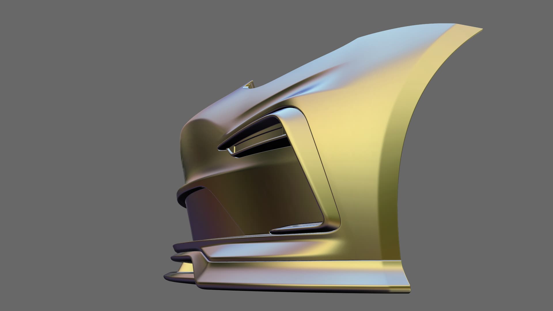
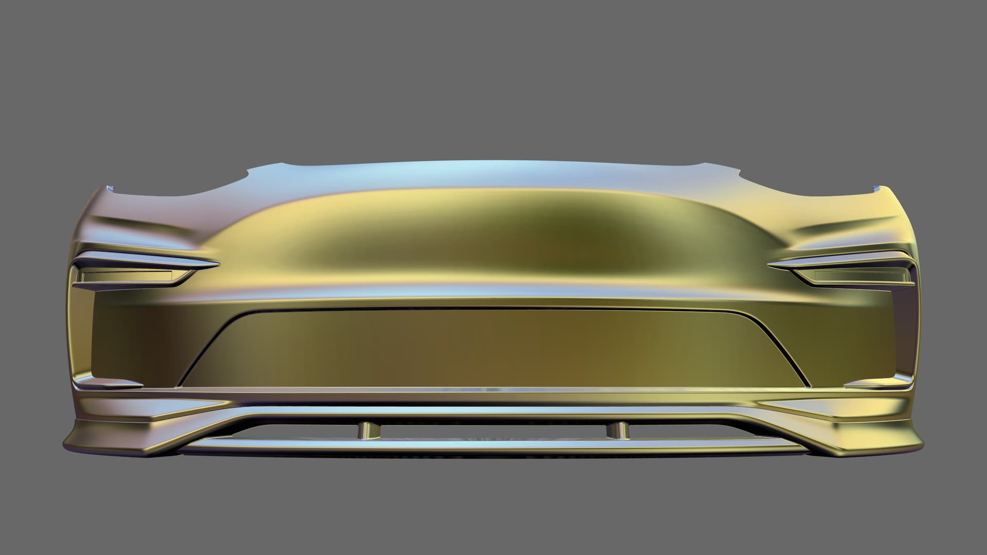
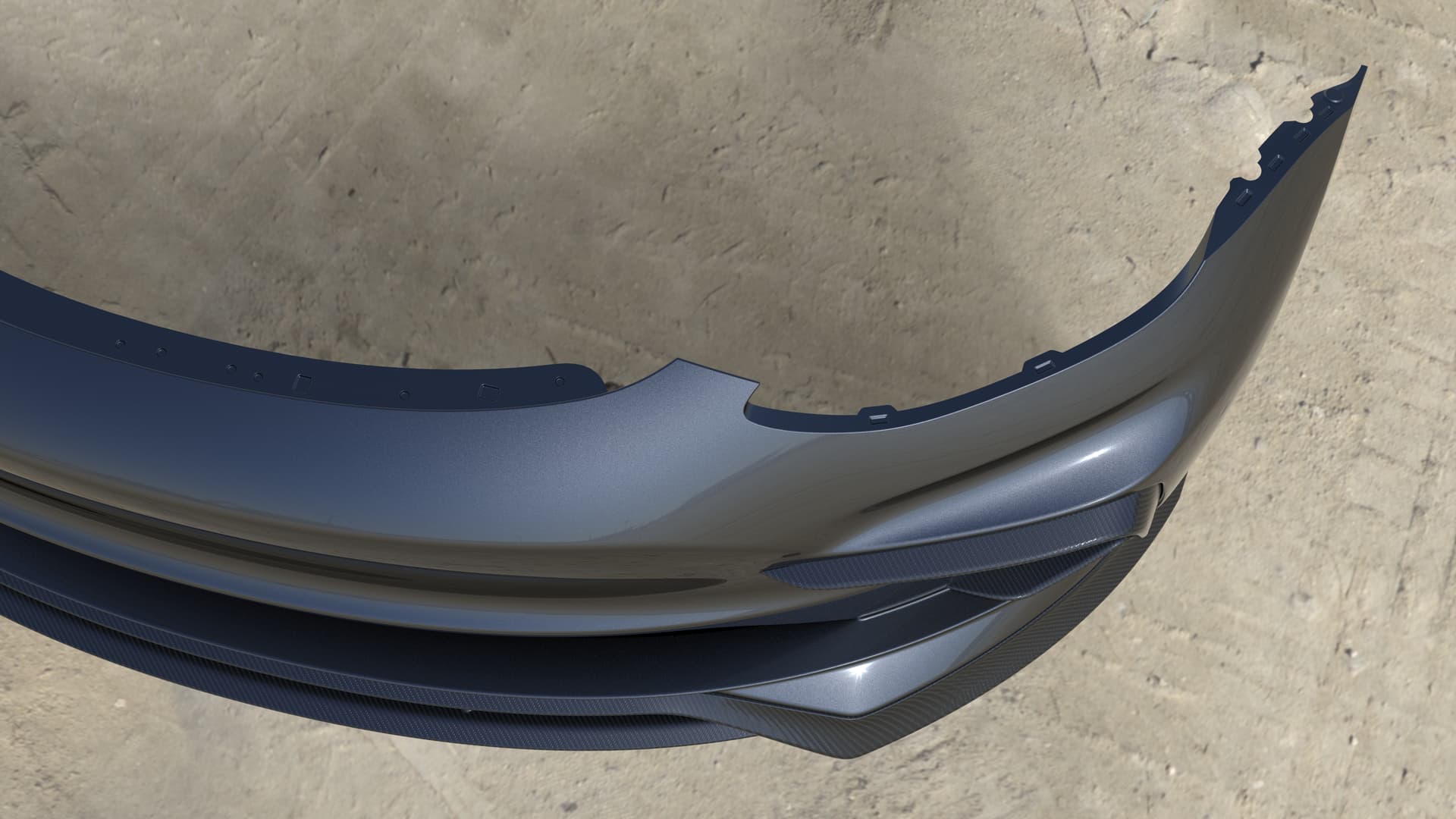
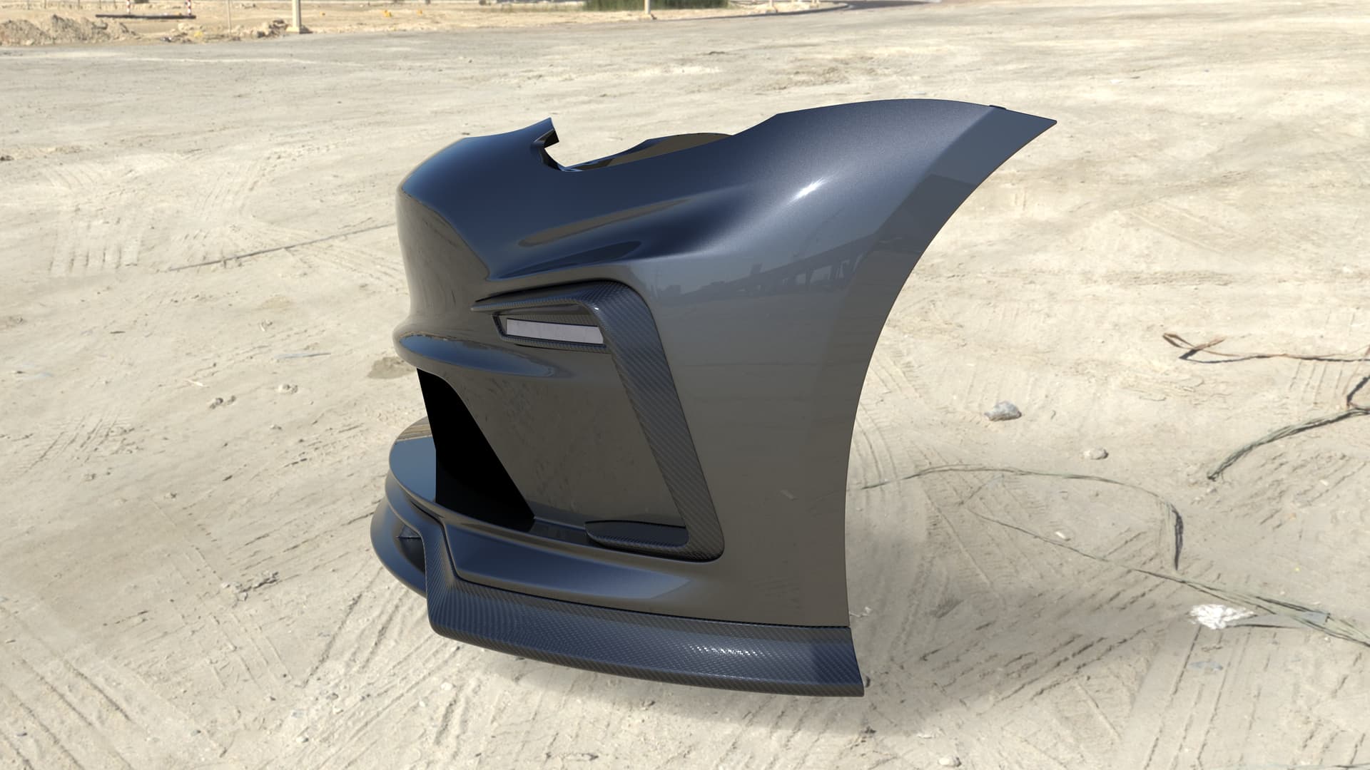
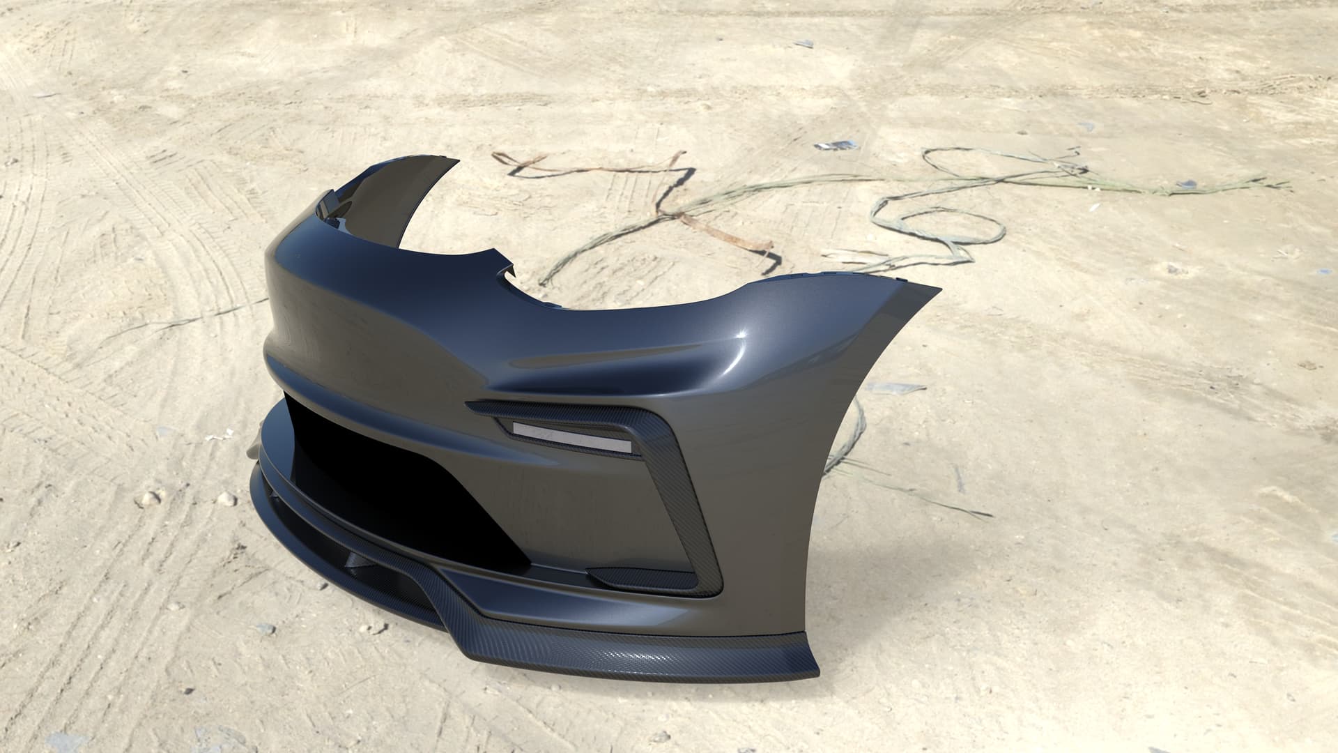
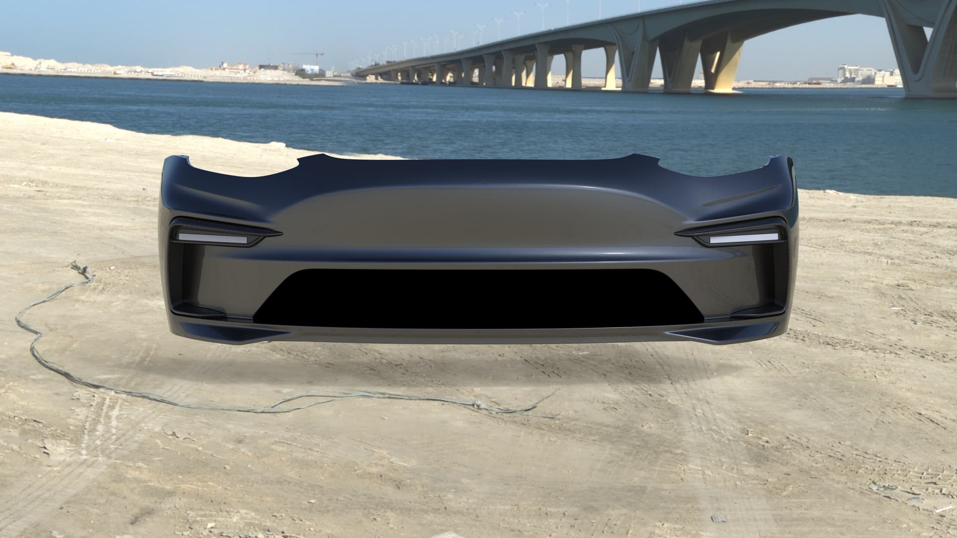
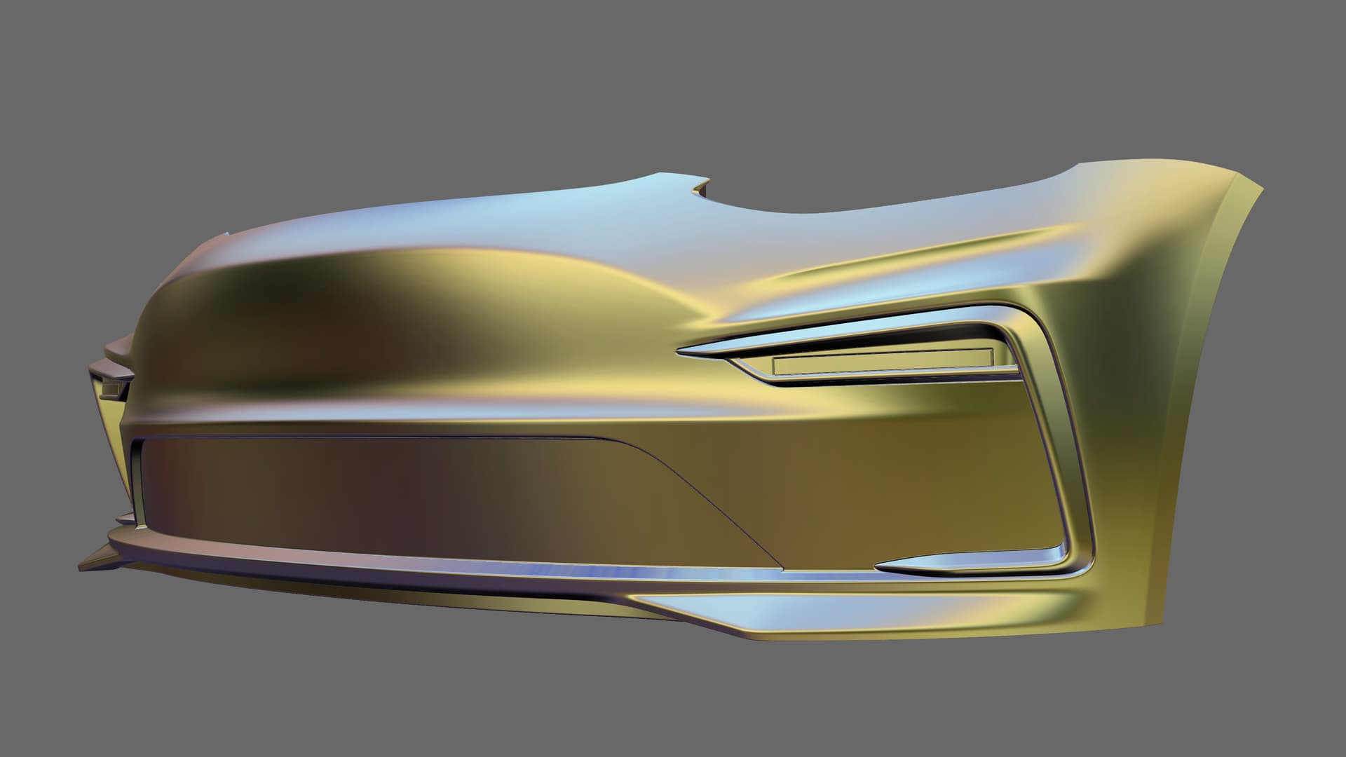
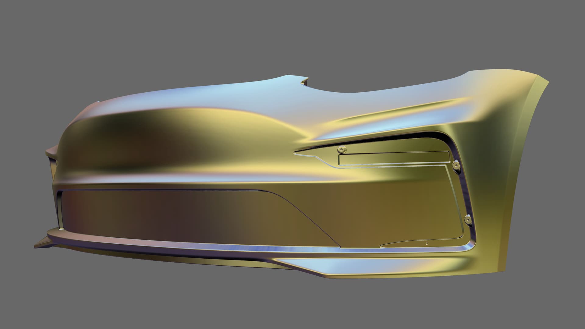
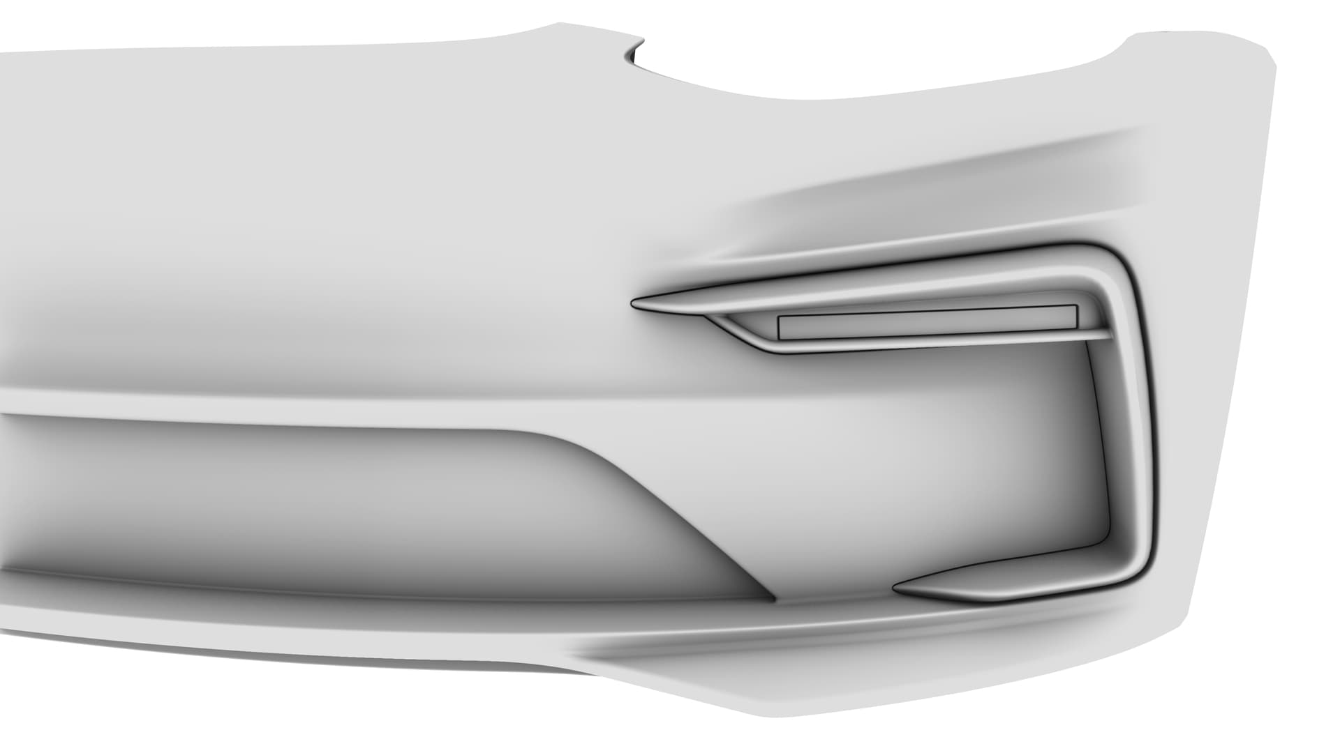
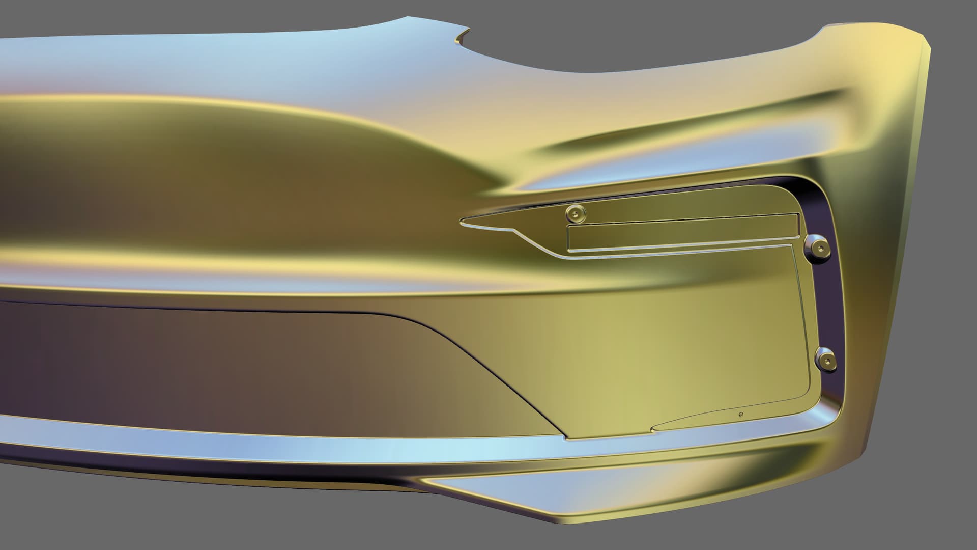
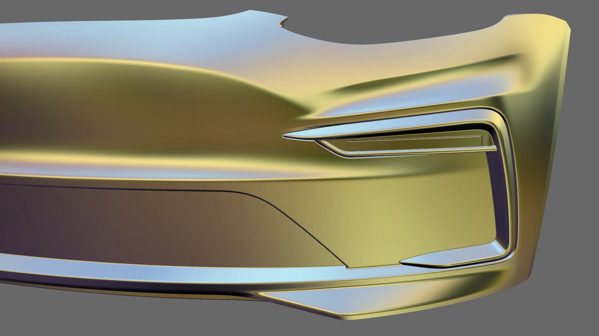
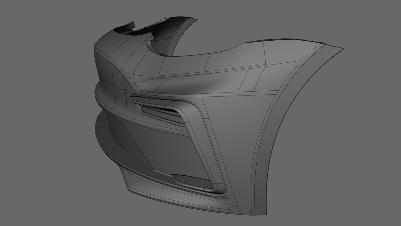
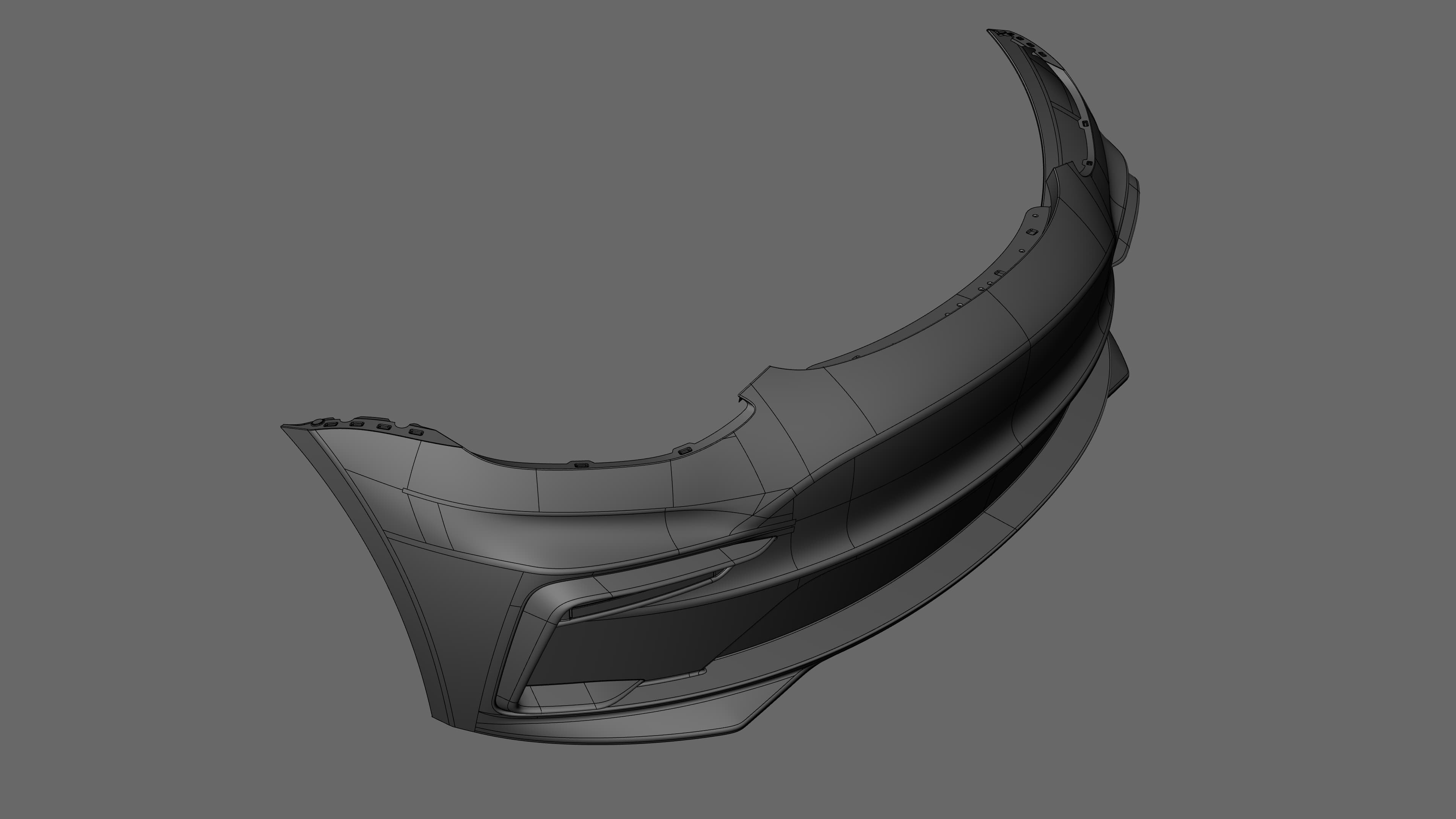
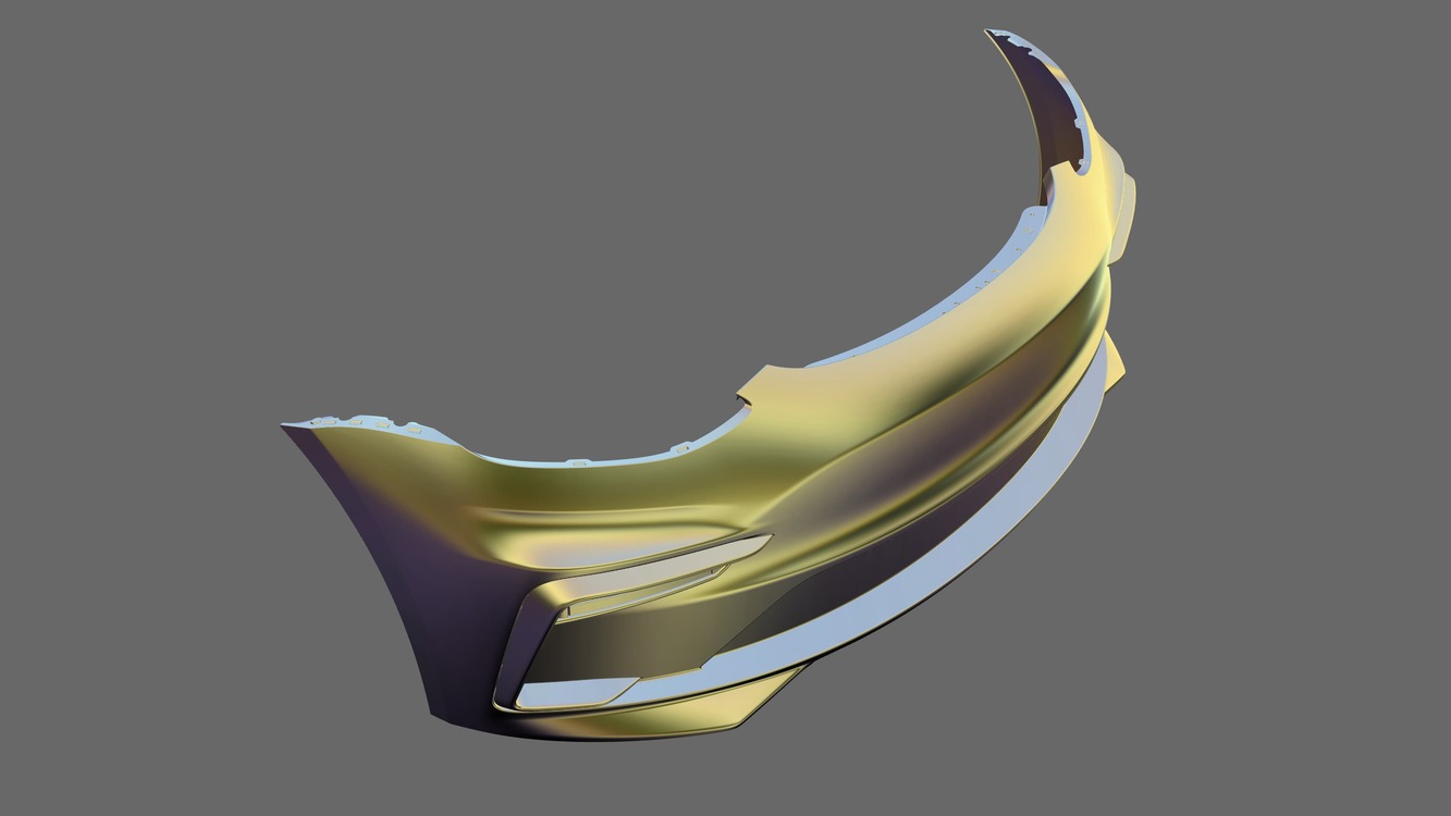
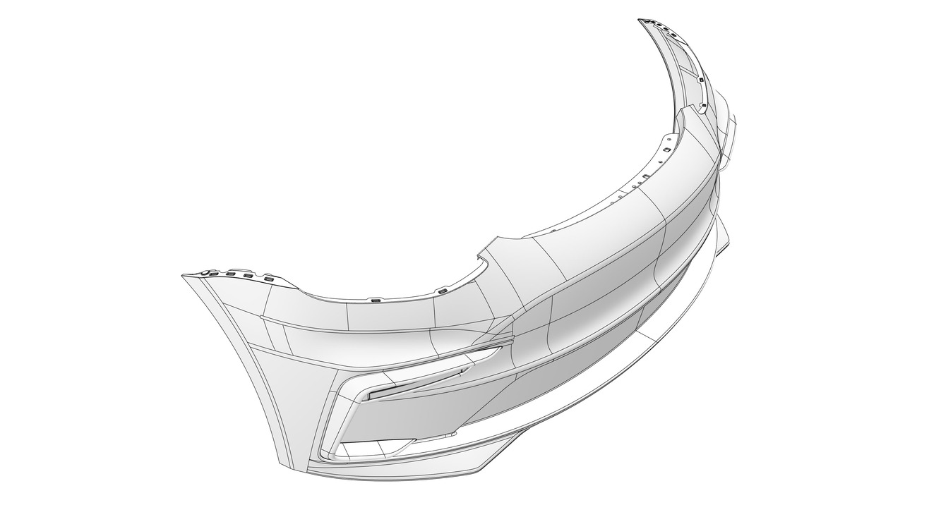
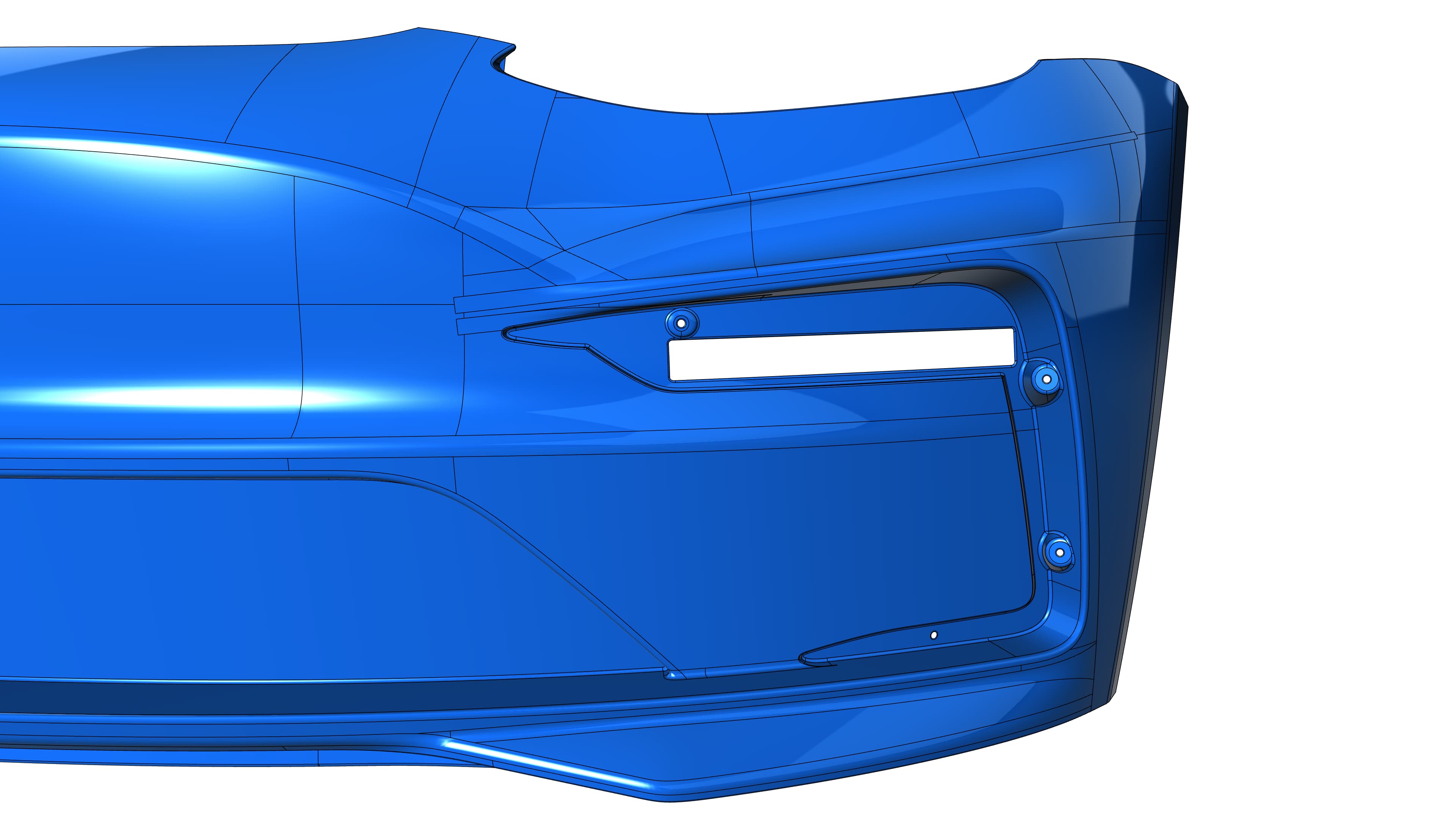
This is still a WIP project, so in the following days and weeks I will make a front splitter, an underbody streamline pane and will complete the engineering part of the DRL housing with mounting points and structural supports, which is currently only finished from outside. The front bumper is a tuning upgrade for the Tesla Model 3. I will post some additional pictures of the remaining parts when they are ready.
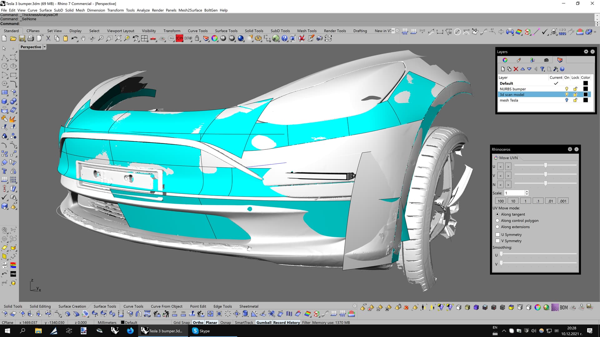
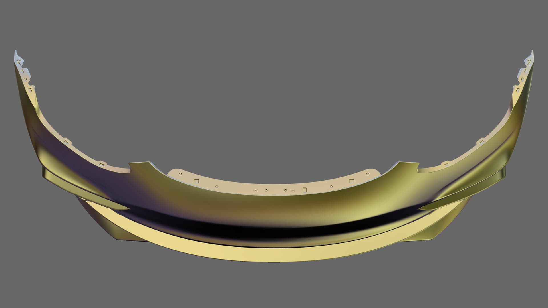
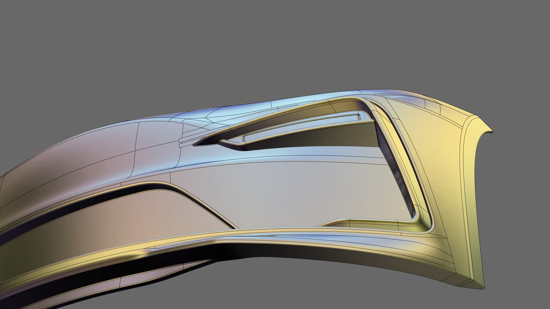
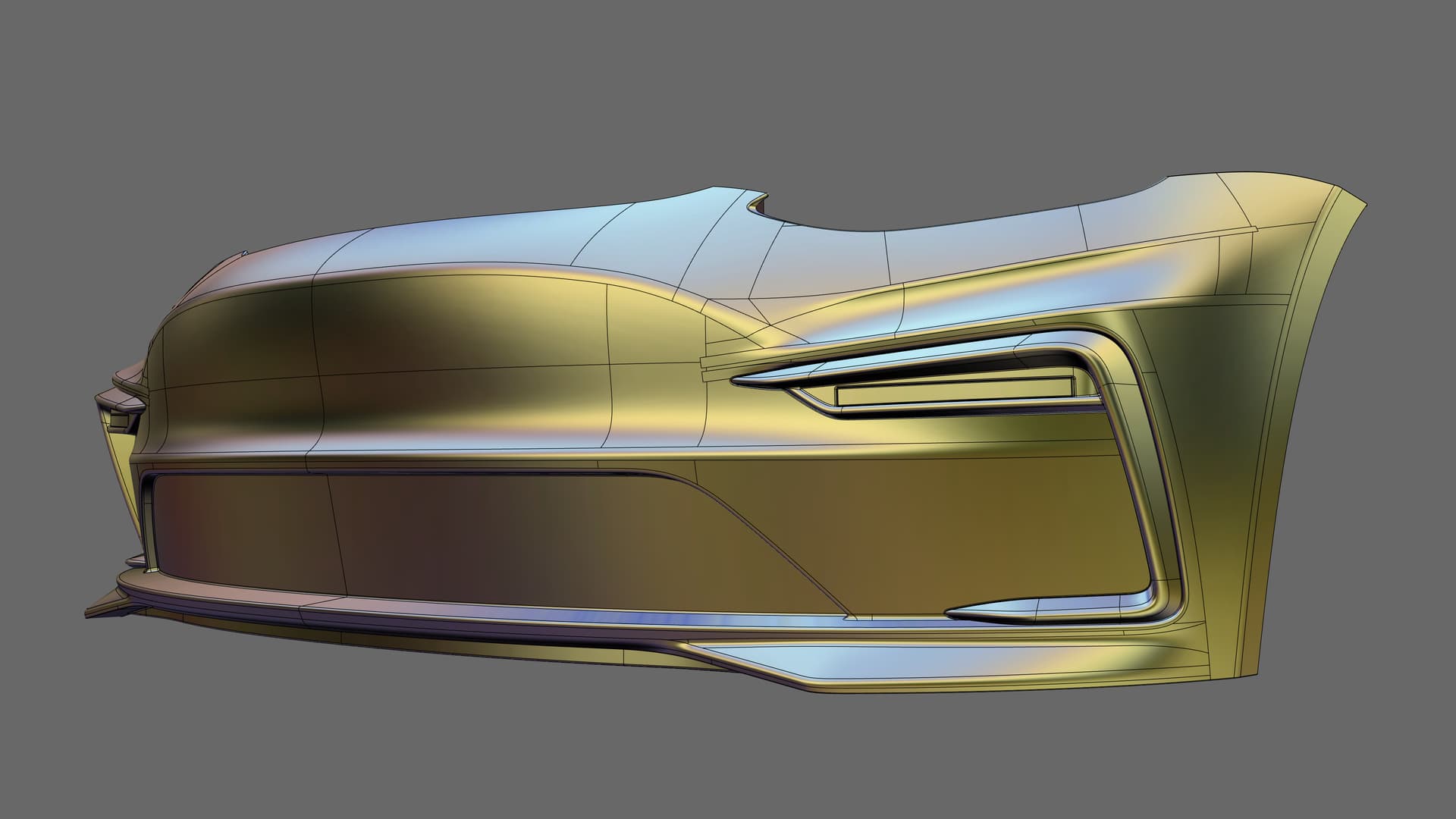
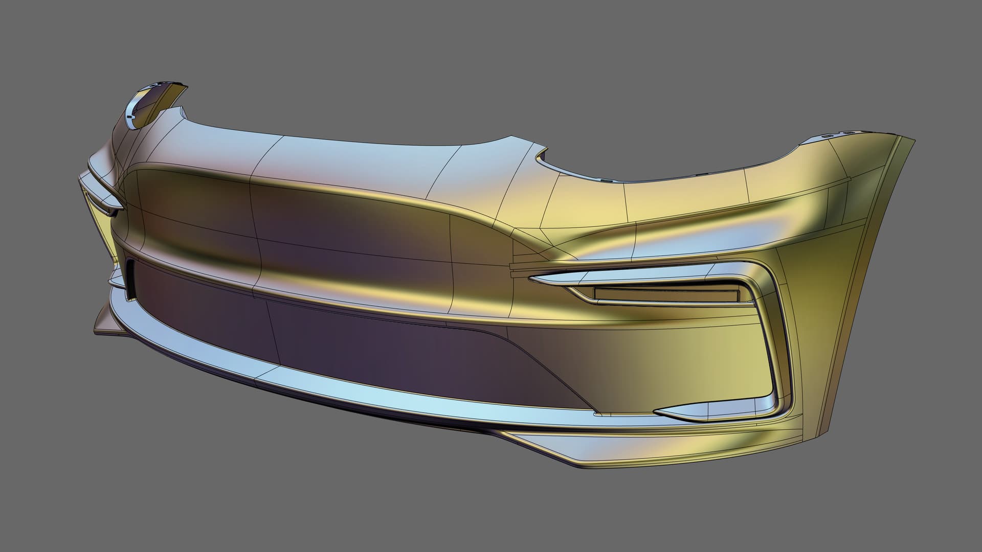
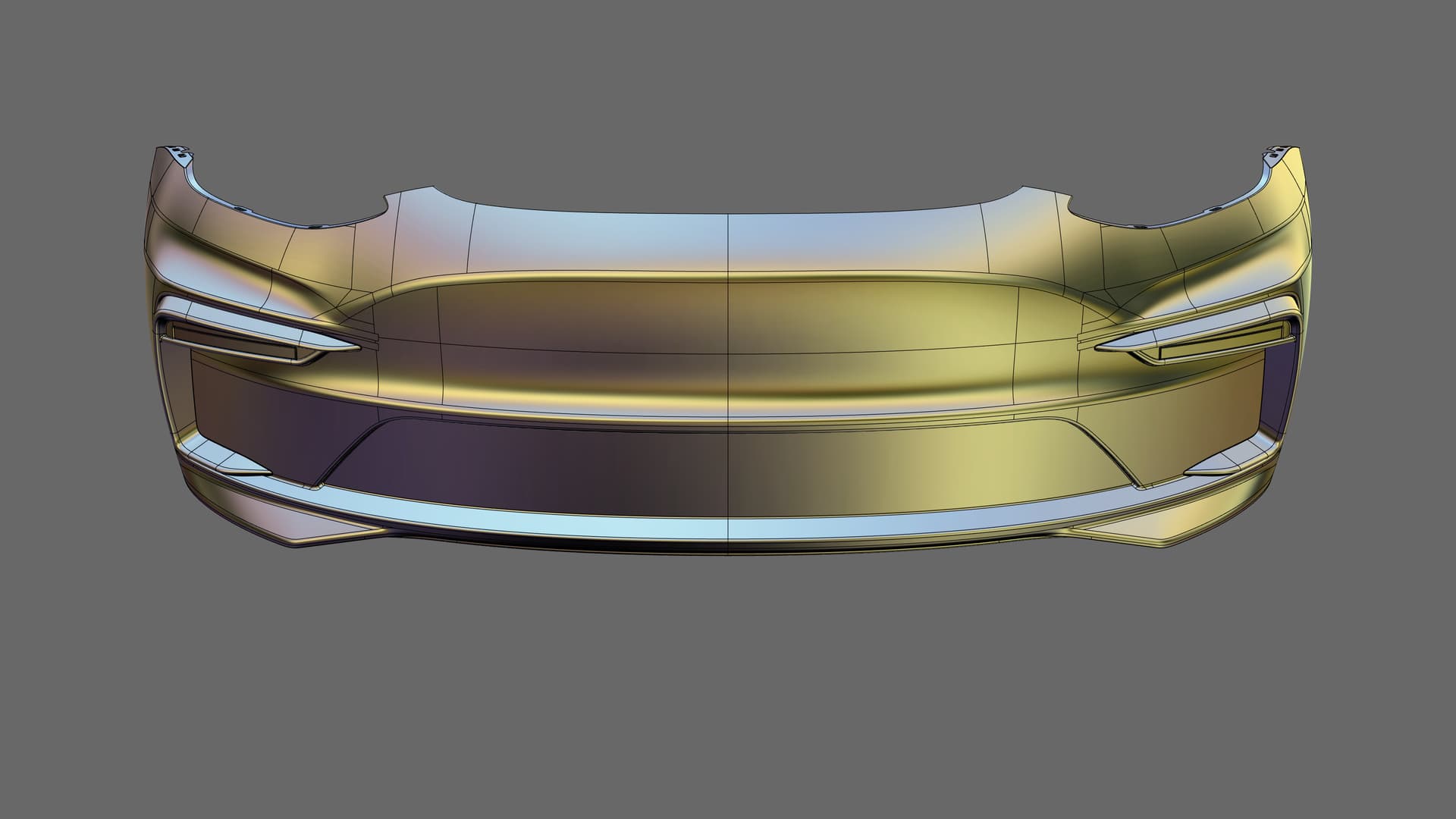
I used 3d scan data as a reference to create the NURBS surfaces within the required tolerances, and I was generally happy with the improved tools of Rhino 7 and especially the “Edge continuity” tool which is a must have while using “Match surface” and “MoveUVN”.
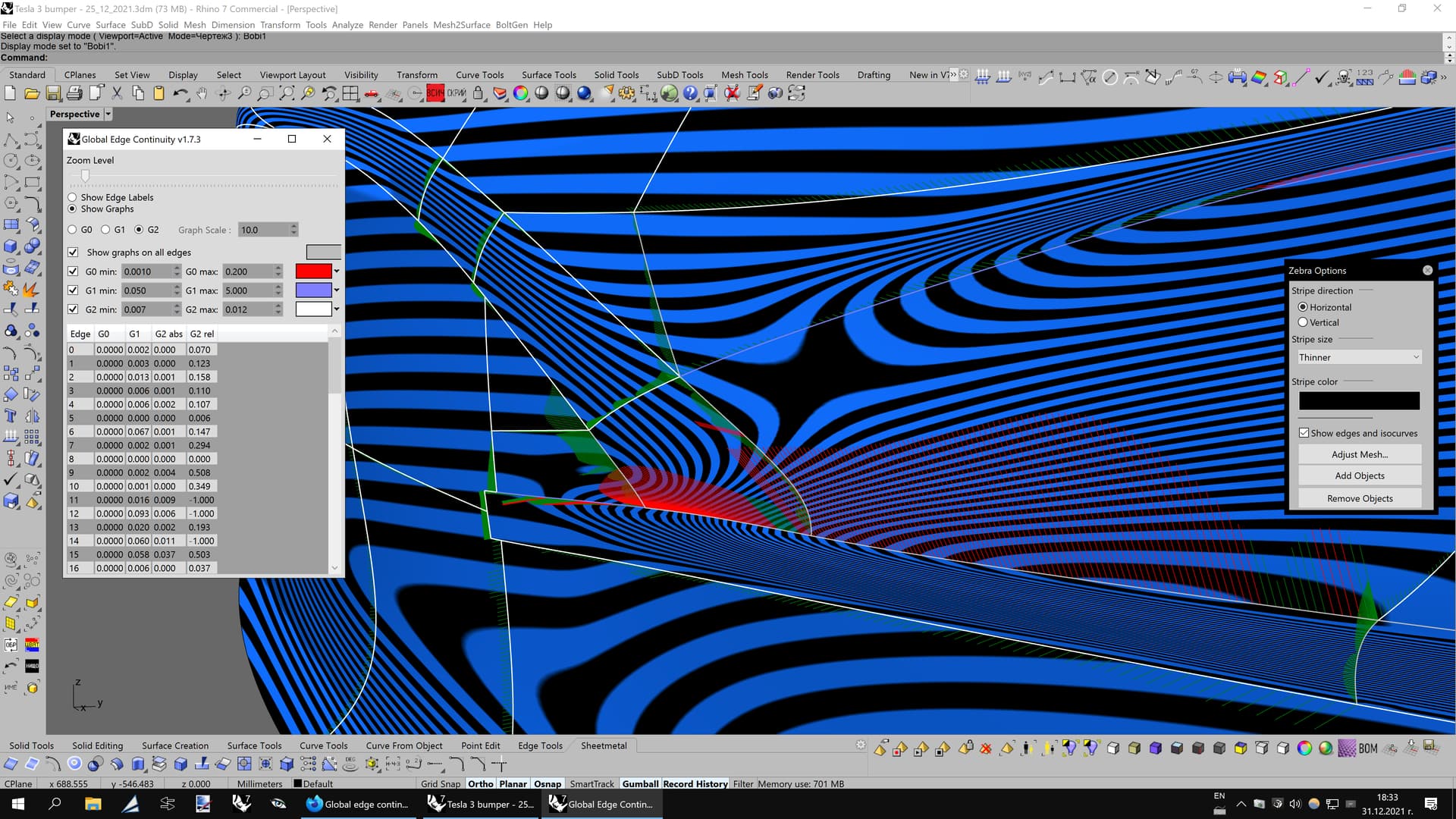
I would like to thank @Gijs for developing his great “Global edge continuity” tool that I also used in this project in a later stage of the work. It’s capable to handle multiple surfaces at once and selection of surface edges to analyze is much quicker compared to the standard “Edge continuity” tool. It reminds me of what the VSR plug-in offered for Rhino 5 years ago.
With regards to the question above, there are two main ways to create NURBS geometry on 3d scan data in Rhino without plug-in such like Mesh2Surface:
Use snap to draw curves with the ! _InterpCrv command directly on the point cloud, then use some of the surfacing tools to build the NURBS patches.
Place a surface (with 4-6 control points in each direction) relatively oriented towards the normal of the mesh surface, then show its control points, select them all and run the ! _Pull command and select the scan data as the target. Rhino will pull the surface quite accurately on the 3d mesh, though there may be a slight deviation (after all, it’s the control points that are pulled, not the surface itself) and you may need to slightly adjust the control points along their normal direction with the “MoveUVN” tool to make the surface exactly align to the point cloud. Sadly, there is still no “Pull surface on mesh” tool in Rhino, but this little trick does the job in most cases.
Here is a simple video tutorial that I just made to show the 2nd approach, though I used “Offset surface” instead of “MoveUVN” to raise the pulled surface:
Thank you for this excellent video! It seems like you are achieving this through manual surface manipulation.
In the case of drone capture, I have a point cloud, with the issue that ground points are not there because the drone only sees the trees, not the ground underneath.
The 3d terrain you posted above reminds me of the similar technique that “Google” used to capture 3d terrain for the Google Earth program, via capturing photos from different angles from a plane flying over the cities. Looks like it’s inevitable to have those blind spots around trees since the software can’t distinguish the shadows from the actual terrain.
An alternative is to use Patch with Starting surface option to “pull” the surface to the mesh. This has the advantage that the surface, not the control points, is pulled to the mesh. If the mesh is very dense the user may need to first extract a set of points from the mesh with suitable density. https://docs.mcneel.com/rhino/7/help/en-us/index.htm#commands/patch.htm
Another way to make a more accurate surface on 3d mesh is to rebuild the initial surface with at least 15-20 control points in each direction, then pull, then rebuild the resulting surface again to simplify it with 4-6 control points in each direction.
I love seeing your models, thanks for sharing.
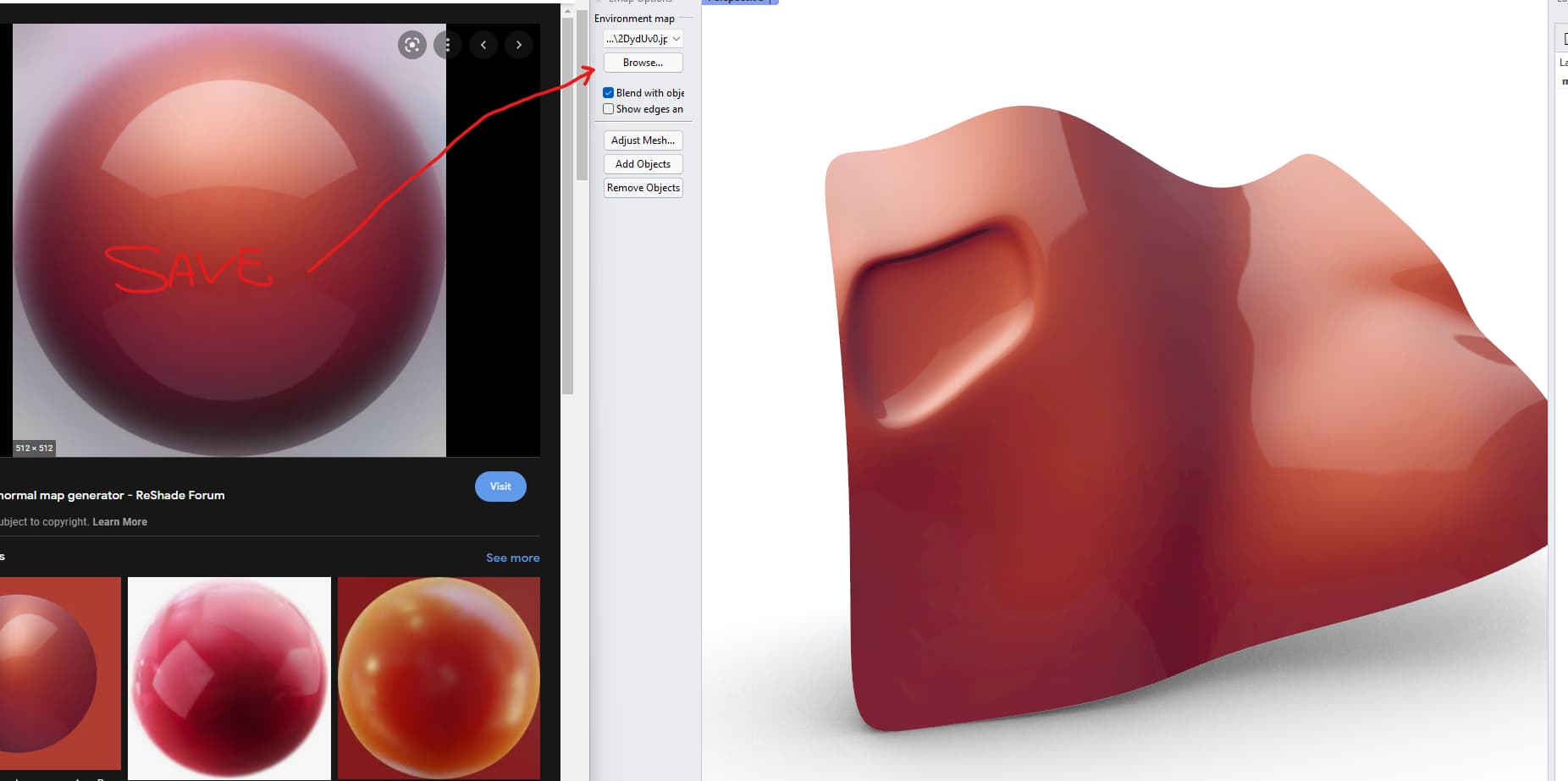
It reminds me of the good old nurbs-moddeling-days I used to be a modelling nerd, but these days it’s all mesh as I work with landscape architecture. But it reminded me that I wanted to mention that you can use any image for that. Just search for matcap carpaint in google and find one, save it and pop it in:
You can also set it up as an matcap environment so all materials will reflect them with out going into emap analysis, just use the rendered mode. Are your top images renderings?
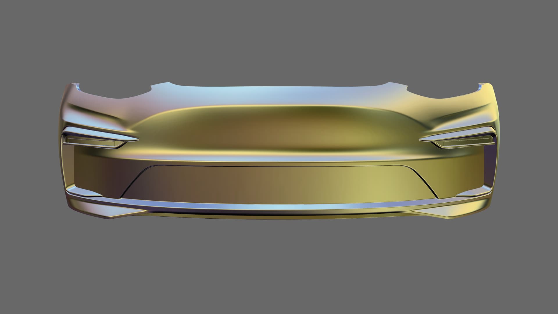
Thank you! I will check that paint type which you suggested. I used a basic car paint material in Rhino 7. I have nearly zero experience with materials, as I mainly devote my time into modeling and engineering of the actual geometry for manufacturing purposes. My top renderings were made in Keyshot 8.
Very nice work. My work is almost the same field, So I admire your work very much. It`s not very popular. I model body kits for cars over 3d scans prepared also by me (last few years). I hope to share here someday some of my private projects (NDA in most cases). I convert Subd into NURBS in some cases to do nice blends. I create offsets over meshes as the last step.
Your shapes are very nice I wonder how it looks on a car. You should do some photoshop mix to show how it looks on the car. I`m sure it looks amazing.
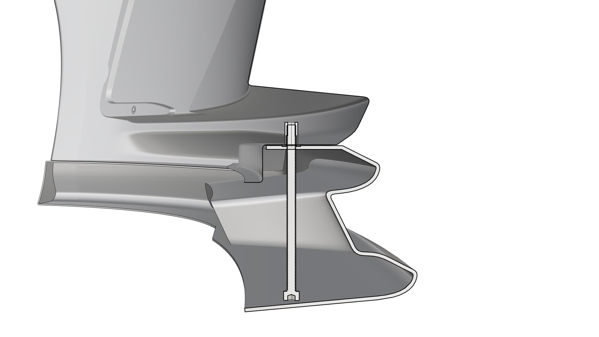
Please tell me do you create your offsetting work after make all tiny blends and fillets (as you said before with manual adding thickness to outer shell radius)?
I may show you my private work for my own car (mirror cap) but the same workflow as usual. That cap was only about 10 hours of modeling. Still without offsetting and snap-fits.
I also create 3d scans of cars alone (structured light scanning and photogrammetry).
The scan below is a structured light scan.
This will be 3d printed so small pinches are not so crucial.
I hope to share more serious private work with you in future (front addon with vents and grids) also dedicated for 3d printing purposes.


")