Hi everyone,
to get a 3D-printable body I wanna build a watertight mesh from scratch. Of course it needs volume. This will come later. At the moment I’m stuck at another stage.
I need to combine/weld meshes together.
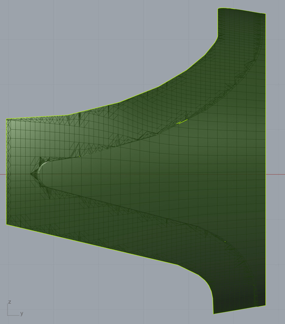
Because I will deform a portion of “mesh A” with attractor curves I split it into “mesh A_margin” and “mesh A_inner”. “mesh A_margin” is the one I will deform. To get a smoother deformation I want more vertices. In the green group you can see what I tried so far to increase the resolution. Destortion/deformation will be zero on the border to “mesh A_inner” and maximum on the outer naked edge of “mesh A_margin”. But because of the different vertex count of the two meshes on their border the welding doesn’t work. I still end up with naked edges between them.
Yes, I know, I could simply increase the resolution of the original mesh and still only distort it where I wanna distort it. But in the end I’d like to have one mesh with different density in the two regions.

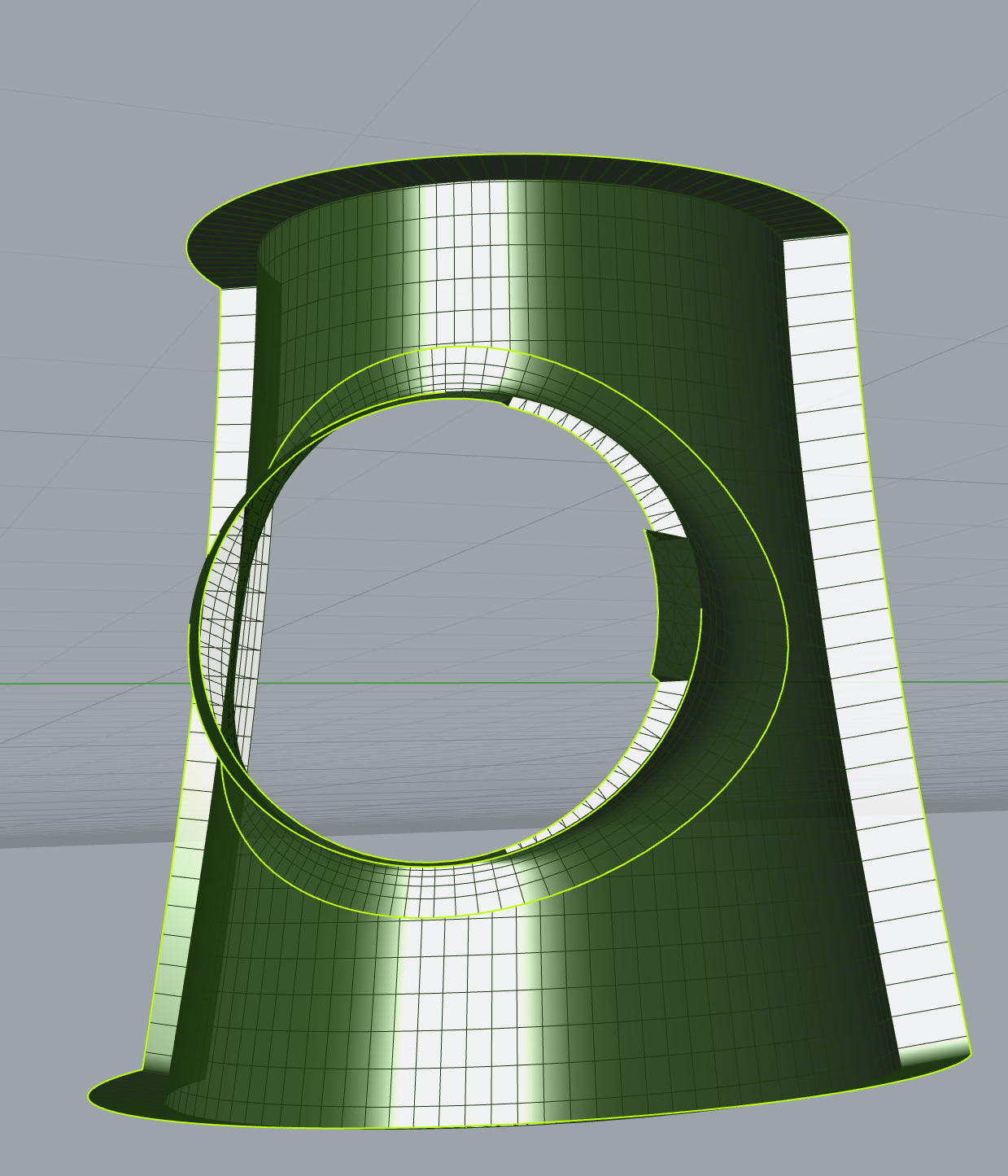
The same problem occurs on the mesh(es) you see on the right. “mesh B” and “mesh C” shall be connected with “mesh B to C transition”. When I try to weld those three meshes I get naked edges on their borders.
Where “mesh B to C transition” touches “mesh B” the reason might be that (like in the first example) vertices do not align but at the border of “mesh C” and “mesh B to C transition” they definetely do and still there are naked edges after welding. I do not understand why or how to fix it.make_watertight_meshes.gh (277.4 KB)
The best solution I found so far for my problem came from Rolf: Achieving what a 'polygon bridge' tool does (with miss-match poly count) in Grasshopper - #3 by gustojunk
With his C# script I was able to create a mesh between two polylines with different segment lengths. After welding I got this result (First I moved the two meshes a little apart to create a small gap):
make_watertight_meshes_C#-bridge.gh (323.2 KB)
There are still some naked edges left. I don’t know why.
I recognised that when I directly use all the vertices of a naked edge to create a new mesh from there, there are no naked edges after welding the new mesh with the mother mesh:
But this knowledge doesn’t solve the issue I have with the meshes “mesh A_inner”, “mesh A_margin”, “mesh B”, “mesh C” and “mesh B to C transition”.
Since I want to build an online configurator (ShapeDiver) with that, I’m somehow limited to the (quite broad) arsenal of third party plug-ins they support (https://support.shapediver.com/hc/en-us/articles/360015208052-List-of-supported-third-party-Grasshopper-plugins)
If someone of you has a solution or could point me in the right direction,… I’m grateful for any help.

