While I am still a beginner at GH I have been trying to learn something complicated. I got stuck in this stage. because I am not able to figure out whats the best way to do this.
As seen in the images i have a stepped profile through which i want to sweep my profile shape. But I need the normal of the extrusion to be towards the centre. I hope that makes sense. Whats the best way to do this using grasshopper? how do i align the sweep towards the centre if i have to sweep these all around the circle? Thanks in advance
that was really good help for me. I will try to use these complicated nodes and learn more. But I was trying to do the same for a segmented with non-planar surfaces. I am trying to use perpendicular frame but I am stuck with how to set the evaluate surface and closest point to get the surface normal a each vertical mullion. Thanks!
Just seen that Kim has replied again, but I’ll share what I was going to post anyway on this.
Agreed, your second attached file really tells us nothing, so I just going off your intention from the first post that you wanted to align sections to a surface of some kind. In this example, I have just made a geodesic on a generic surface to show how you might a) evaluate points and get the normals, b) align the planes according to these normals using the Align Plane component, c) loft through some orientated rectangles set on those new planes. I won’t post a file as it’s quite a simple definition.
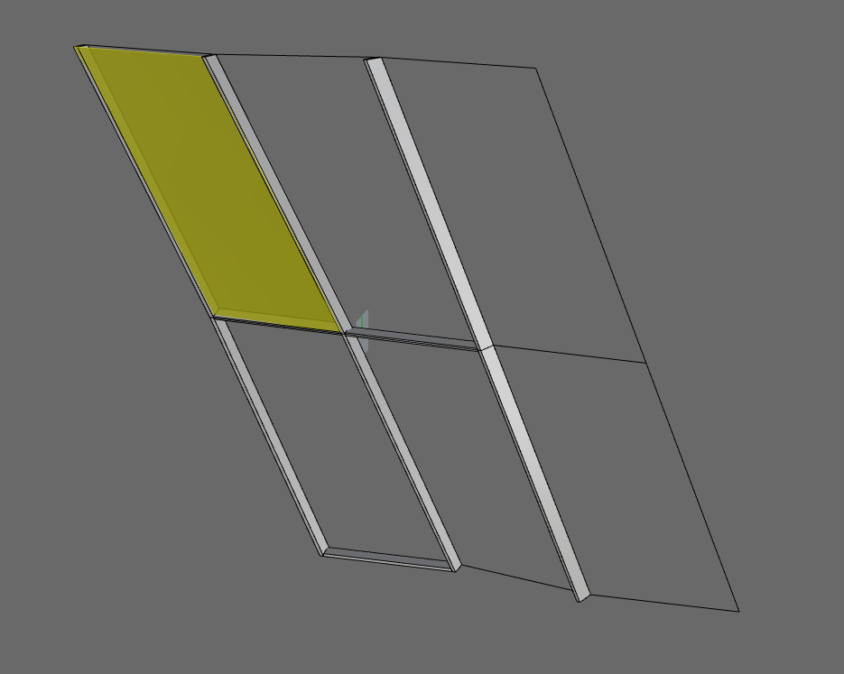
Basically this is the idea. If I have a wireframe of random panels and I want to generate mullion to support those panels. And most importantly the mullion must bisect the two angles. I hope that makes sense.
Hi John,
Yes. That was my mistake I should have made the question more clear. I just modeled some in Rhino to explain the situation. I hope it’s helpful. Thanks
You need a guide vector at each connection to align the mulion profile. The best way to do that is actually to turn your line network into a mesh (using the Weave Back component from Weaverbird, or else just by making a mesh yourself in Rhino) and use the averaged mesh vertex normals. I have internalised such a mesh in the definition below.
Then you can set out planes to orient your profiles before extruding them, however you wish to do it. In your case I presume vertically, so the top bit of the definition is just picking the curves that you wish to extrude. It then joins them, sorts them and lofts them into the mulions. The profiles are oriented by combining the mesh normals with the XY plane (you can just use the normals if you would rather, however I’m going off your first image from before). Note that the mulions with your line network will inevitably twist along their length because what you have here is not what they call a ‘zero-torsion offset mesh’ (big words eh?!).
The offset ‘surface’ panels are then just made by moving the mesh vertex points in the direction, not of the mesh normals, but of the planes we made before for the mulions. Then just make a surface from the mesh face boundaries. I hope this is your intention, can’t spend too much more time on this though as Kim has also burnt some time here - you really have to explain the question in detail in the first instance in order to get better answers, but anyway I hope this helps you in your mulion quest.
This was exactly what I had in my mind. I understand the twist part, but like you said it’s inevitable. And thanks for explaining the process it was really helpful. I am gonna start to learn weaverbird more. Thank you very much.
Thanks to Kim as well because the other script that he did also was very helpful for me to learn.