Hello, everyone. I am a beginner with Grasshopper, and I would like some help learning how to extrude a profile along a rail. I apologise in advance, as I think this is a common problem that has already been solved many times on this forum, but I cannot solve the problem or understand how to do it based on the forum posts. I have even tried the C# scripts found on the forum and the Python scripts by claude/chatgpt and gemini, but nothing works.
PS: I would like to point out that the orientation of the profile, as shown in the images, must be maintained on all segments of the rail. Thank you.
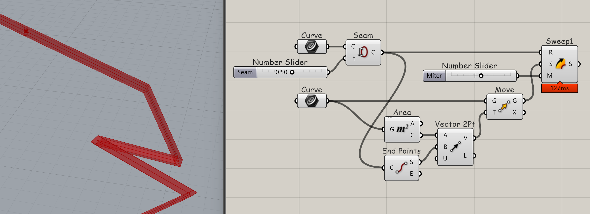
The profile needs to be placed at the start of the polyline, and the start of the polyine best moved to away from of corner of the polyline, because otherwise the Sweep will not miter there.
Thank you for your reponse Volker, But is it possible to have all intersections trimmed like this ? Sorry if I didn’t specify that in my original message.
is this the geometry you’re after ?
i scaled the profiel by x3 to make the challenge more visible:
depending on your zick-zack the start and end rotation (profile around rail) will not match
I am not trying to trick anyone. I just sometimes don’t know know WTF I am talking about and need to be called out on that.
Sweeps are decievingly complex and confusing to me. I understand that the profile follows the curve frame and that that often causes the profile to twist in an unexpected way. In most cases I don’t know how to deal with it. It is strange to me that the profile orientation is tied to rail curvature and can’t be mapped to it. Feels primitive and restricting. The same problem exists when creating ruled surfaces from curves and other free-form surfaces.
Thank you Tom for your time, but this is not the geometry I want. I need a geometry with the correct dimensions of the profile in the file I drop in my orginal file. In addition, I notice that your geometry shows changes in the orientation of the profile on the different segments of the rail, but I want to keep the original orientation of the profile uniformily along the rail.
Thank you for your time René, but the result is not what I want, because the “rotate” option changes the orientation of the profile according to the segments, which is not what I want. I want to keep the original orientation of the profile along the entire length of the rail and have a trimmed geometry at the intersections.
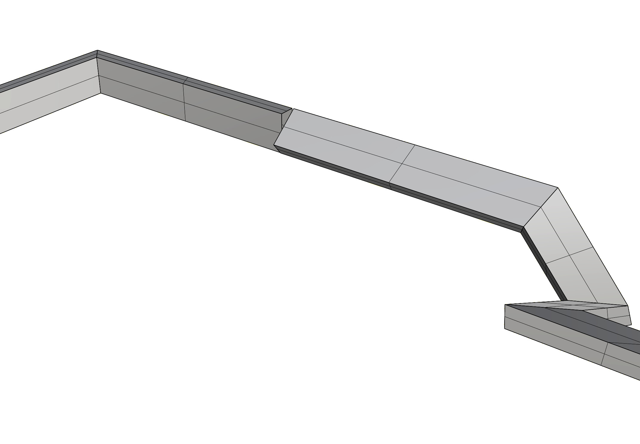
my approach is like cutting a wooden profile. the section is the same for all segments.
the angles of the cut are defined by the mid-angle-plane between two segments.
… because i use one loft per segment. but same can be done by extruding / spliting.
There is a difference between the geometry and how it is represented by the actual (nurbs) surfaces - so if you need a special representation, we can discuss this in a second step.
This ‘original orientation’ of your rectangular section is only original on its original line, on its own local plane. How would you ensure/maintain this orientation on the next segment if you were building this ‘sweep1’ manually?
—
I set up my ‘loft/extrusion’ method too and haven’t returned to it.
Therefore I agree with you, Volker and Tom—and with Volker twice because who knows how sweep works
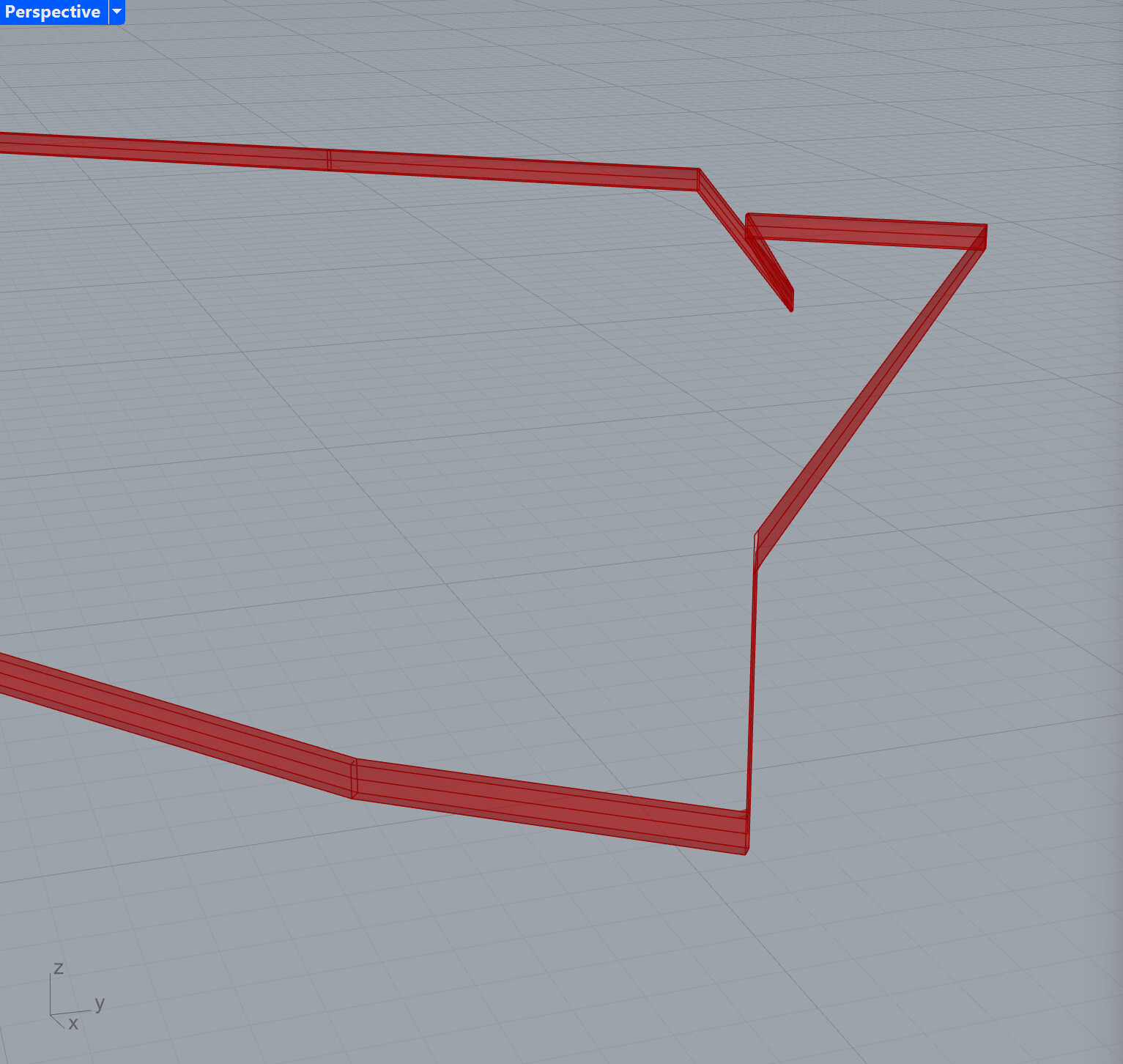
No, I meant that you want trim. Trim will rotate the profile against the curve frame so that it arrives at the corner in an orientation that can be mitered with the subsequent section of the rail. In my version this works:
and the fact that Raoul cannot upgrade his Rhino to the current version gives me suspicions about the type of program he is working with.
The rotate option of Sweep1 extrudes the profils along the rail and rotates the profile around corners to meet the starting profile orientation of the next rail segment.
Secondly,
what do you mean by “keep the original orientation”. In relation to what? World coordinates? The curve frame? If it is the world coordinates, this would be the same as using Extrude Along with the profile against the rail, but will produce flat planar surfaces in particular sections of the rail. See here:
If is in relation to the rail, Sweep already does this. I have the hunch that what you really are after is the profile oriented to the rail, but adjusted to maintain vertical alignment. For this you may have to use a different method to sweep, Loft for example. Or you could cut out the vertical section of the rail that is causing the twisting problem and deal with it separately.
I played with that but hit a wall right away with the ‘found’ planes of what you wish would be beautiful ellipses resulting from a basic pipe, but they won’t be — however, also: I’m no expert, so I don’t know—though if piping won’t help because the planes won’t be useful then why not determine these ‘90 degree’ systems first, which sends us back to the conundrum of:
I’ll just keep my mouth shut lol I don’t know what anything wants!
Here’s one lazy way to (1) ensure ‘same profile extrusion(s)’ in 2D in order to demonstrate in 3D that (2) it’s a useless example! Because of all the things already mentioned by Tom and Volker here .
And given I’m less proficient than them I’ll await another contribution