I want to share a relatively easy way to draw Tungsten-Inert-Gas welds. The technique could also replicate MIG (Metal Inert Gas), with some adjustment. The technique could theoretically be automated with Grasshopper, or a Rhino command. First, let’s see the results…
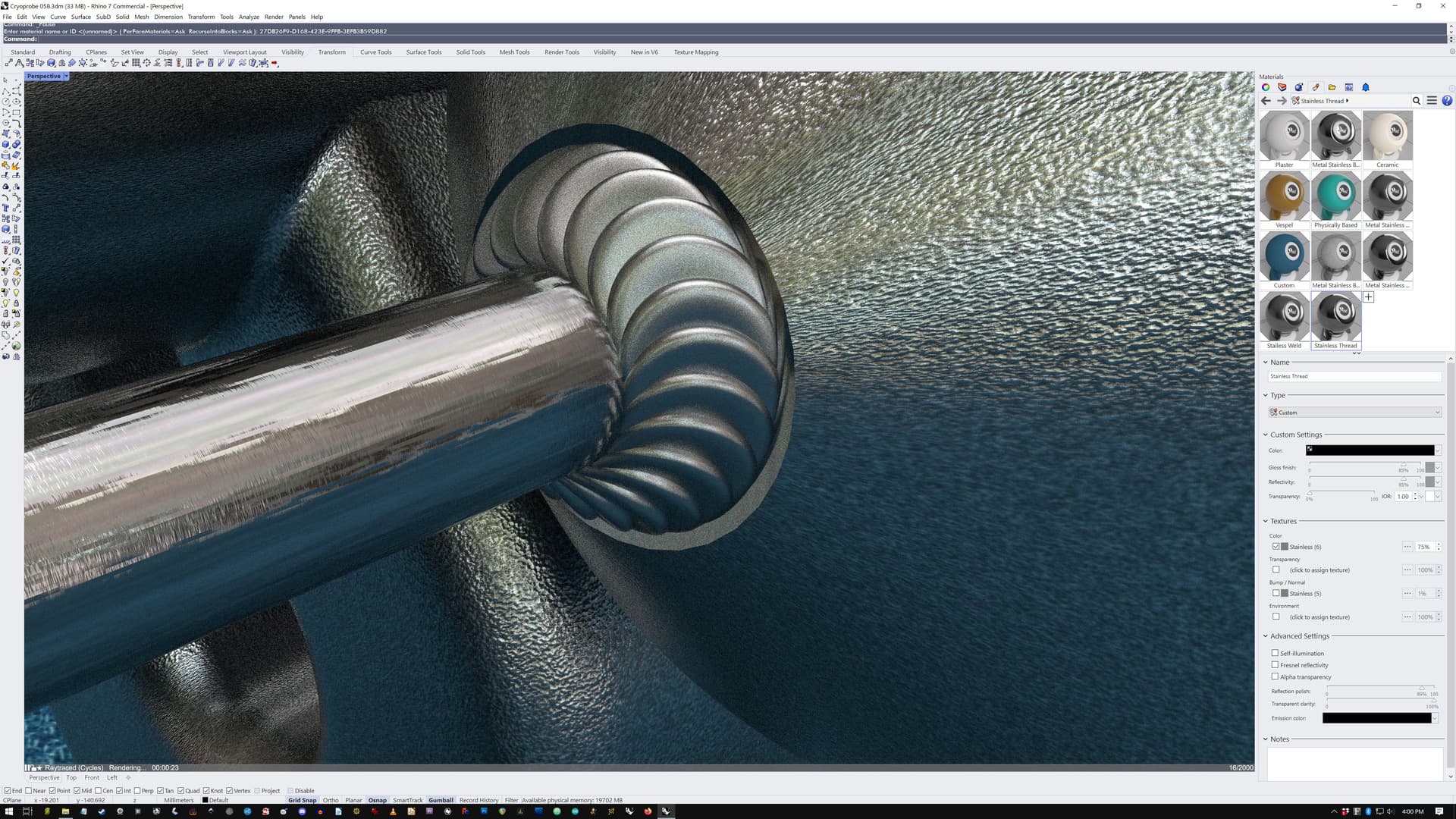
Here, we see a tube connection, a 90 degree, and a more acute angle.

I’m sorry about the materials and mapping, but this is technique used on a tiny 2mm diameter welded tube.
And here we see a 12mm pipe joined to a casting:

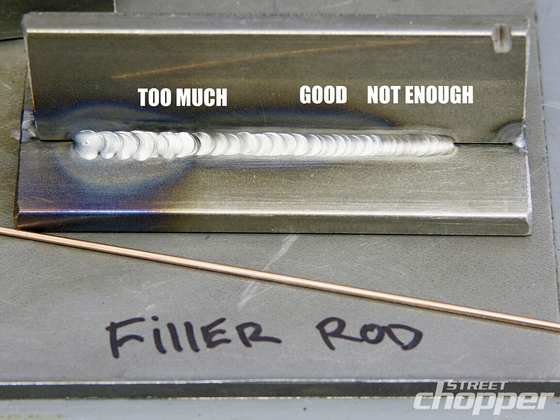
The technique is largely based on how a real weld penetrates the work. This is a drawing of a weld bead:

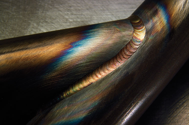
In TIG welds, daubing the weld puddle with the filler material gives this real-world effect, seen in these four following pics of real welds–not my technique.


Likely, you might be getting the gist of what I am doing. I create a curve profile, and then revolve it into a surface. The first shape works pretty well for all but flat butt-welding and deep Vee angles. The 3rd shape would work better for approximating MIG welds or butt welding. I usually use a curve boolean on the shape and the bisecting line to create a half-shape. These shapes are revolve 'd.

The real trick of this technique is to angle the weld-blob in 2 directions. I usually give it a bit of leading from 5 to 7.5 degrees. The TIG welder does this with their torch while controlling the puddle. If you angle the blobs too much, one blob will cut a hole into another.
Then the blob is angled to drop evenly into the joint. While moving the blob, the [TAB] key helps you set the penetration depth along the “throat” line. When doing this, I try to just leave a little “face” showing so we can see the “toe.”

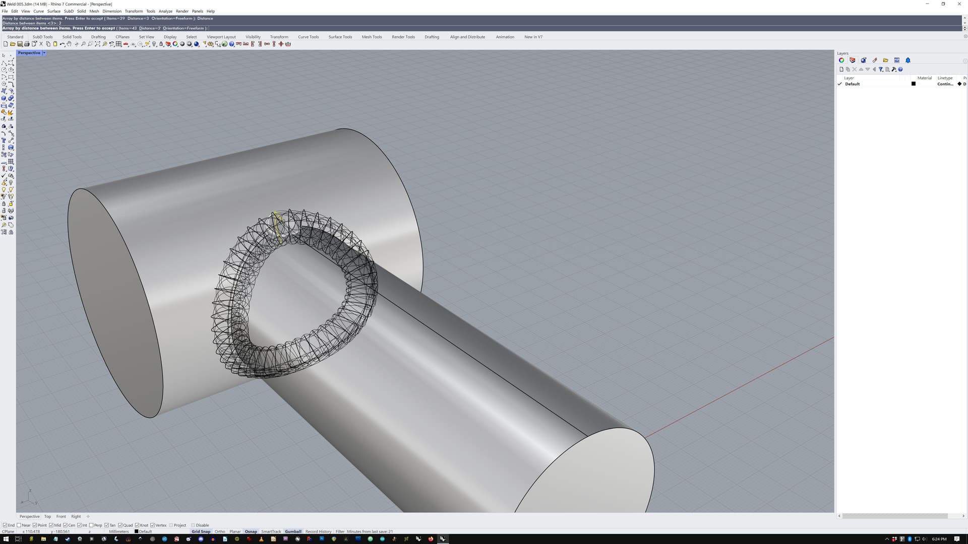
And then the little weld puddle bits are replicated along a curve either copied or using the original seam as long as it is an uninterrupted curve, using Array Along Curve _ArrayCrv like this to achieve an overlap.
Things become more complicated with a deep Vee weld. To approximate the climbing and penetration of the sides the top surface–as well as the effect of gravity pulling the puddle down, the weld blob needs to have the overall shape of a Pringles potato chip. Because it is only one surface, the result can be rebuild to simple thing, as we are replicating it quite a bit.

And here are those runs and the shapes that created them.

The weld itself may be binary Union’ed to the substrate objects, or not. Rhino seems to deal fairly well with this kind of numerous additions. Though, the surface complexity and resultant polygon count has a performance price.
Edit: in the Cycles-rendered results, the weld isn’t union’ed, so it needn’t be merged for decent appearance. The rendering mesh can be set quite low for the mass weld blobs. (Thanks Pascal.)
Oddly, except for the Vee workpiece, the other 5 simulated welds shown here–were all made from the same blob, resized, angled and replicated.
Oddly, because this technique approximates real welding penetration, there may be some use to using it for Finite Element Method. The weld blobs themselves may cause stress concentrators which may give interesting results. The entire weld itself may be union’ed and then subtracted from the substrate–and then that joint may be described in FEM. Sometimes dissimilar metals are used, and can be solved.
Going further, an Grasshopper sketch could be made do these chores. It would seem that the figures of merit would be the size of the weld, the leading angle, overlap, and penetration. As far as shape, we are controlling the center-point on the “face” of the bead. For deep Vee’s the profile would have to be asymmetrical, as seen above, and those could be adjusted per increment by calculating the angle where each weld-blob would be.
Welding is an art, and if you want realistic welds putting some randomness into it, adjusting the depth, angle, and keeping on the line.
Lastly, creating a material for a decal that would simulate the temperature burns at each blob would give it that nice burned straw-to-purple effect.


