Hi @tkahng
Good question - making an initial mesh topology is often a very important part of form-finding/relaxation, and it is not always easy.
This part generally isn’t automated, since it depends so much on the design intent and aesthetics, and what makes a good topology is often quite subjective. Making good ones is a bit of an art and takes practise to get a feel for what works.
Luckily though the initial mesh usually doesn’t need to be many faces - often less than 10 - it is just to get the placement of the boundaries and irregular vertices (internal points where the number of connected edges is not 4 for quad meshes, or 6 for triangular meshes). This can then subdivided to get a finer grid, which is then relaxed.
To create this starting coarse mesh I often just create the faces one by one with the _3DFace command.
Sometimes it makes sense to start with a simple mesh plane or box and modify by joining/deleting faces.
On real architecture projects choosing and refining the exact mesh topology to use is often a discussion with the design team that goes through several iterations.
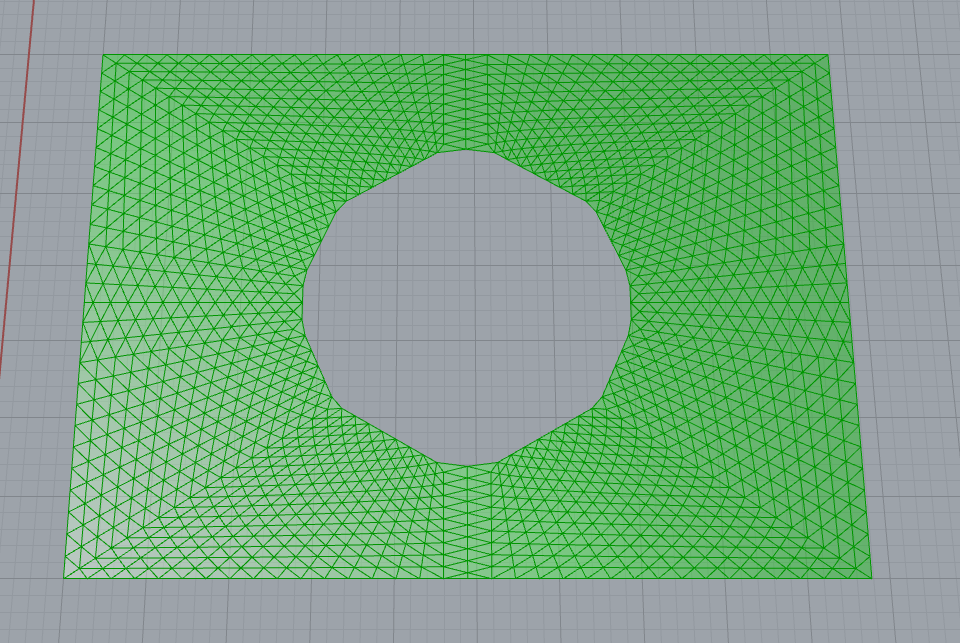
The British Museum file is a more complex starting mesh than most of the other examples because I matched the exact topology used in the real project. This mesh was arrived at over numerous design cycles to get the desired curve flow and variation in triangle shape and there are several quite subtle modifications to the grid.
So it can’t be described so simply as a pure subdivision of a small number of triangles. Rather it can be seen as a subdivision that has been modified by trimming certain parts so that which of the grid directions aligns with the boundary changes as it goes around (or as radial lines which have been divided into different numbers of segments then joined up).
Note the way that for a portion in the middle of each side of the outer boundary, it switches so that instead of one of the 3 main grid directions aligning with the boundary, there are several triangles which are ‘cut in half’. So the valence of the boundary vertices is 4 along most of the side, then switches to alternating valence 5 and 3 in the middle.
Also note that rather than do the same with the ‘half triangles’ at the interior circular boundary (which would have resulted in some rather small triangles), there is a ring of valence 5 vertices adjacent to the boundary.
All this looks quite odd and awkward in the initial mesh, but the magic of relaxation is that it smooths out all these discontinuities, and the end result is something remarkably smooth and natural looking, so that to the untrained eye it all looks quite uniform.
One subtlety of the final mesh chosen that I find particularly charming is the way it visually follows the lines of the pediment of the old building, yet still smoothly aligns with the horizontal edges of the walls on either side:

This roof has become something of an icon in computational architectural geometry, and there have now been numerous papers which use it as an example to demonstrate new meshing techniques, and show it with different topology such as quads, which I often find quite clumsy, as they focus purely on the algorithm while missing the way the real thing combines clever computation with thoughtful human design work.