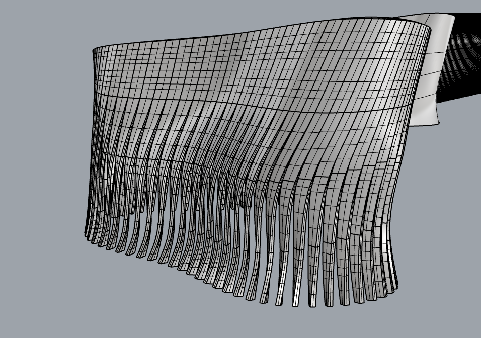
hello, greeting everyone, I’m a student and I’m new to rhino and grasshopper just picked up the basics and I need your help I made this type of surface and I want to apply this louver on it where it starts in a straight direction but at the top, it all turns 90 degrees but I don’t know how because my surface is organic and array on the curve only work on one curve so it didn’t work for me please if anyone could help I would appreciate It.
I attached a similar example I which to achieve
thank you
check out the rhino command called
_flowAlongSurface
the corresponding grasshopper component is called
sporph
search this forum or the www to get more info about or find tutorials.
design-wise, how do you want the stripes to behave or handle the different circumference at different heights ?
will the stripes vary in width ?
or will the width stay the same and the gab will vary ?
post a .3dm file (drag and drop to the edit window) if you need further help.
hope this gives some entry-points - kind regards -tom
I’d need more images from the inspiration project to give you a good answer for how to do this.
I don’t think it’s as simple as just using sporph. I expect it’s based on first mapping curves over the surface, but then they’re varying the densities of the curves, as you see on either side of the entryway. There are many ways to do this, one is “tween through curves on surface” component in Pufferfish.
After that, maybe use the perpendicular frame component, possibly combined with the evaluate surface component, to array rectangles along the curves, in preparation for lofting the rectangles to get what you see in your inspiration image. This gives you an opportunity for very intimate control over the result, because you can play with the rectangles in a number of ways before lofting. You can twist them relative to the normals of your source surface, and you can find various was to space your lofting rectangles and scale them along the curves to get the kind of smoothness you see in the image.
The parametric house tutorial linked above is a good place to start, because the graph mapper is probably going to come into play to get smooth control of your lofting cross sections, but the inspiration project is more complicated than the tutorial.
thank you Mr. Tom_p for your helpful comment
I tried flow along the surface but it didn’t work I have no clue why it just comes straight to the surface
for the sporph I will look it up and see how to make it work
for the design, the width stays the same, and the gap vary
again thank you very much for your helpful comment and kind words
thank you Mr. Tay.0 for the video I tried it but when I add my surface the twisted code gives me an error “1. Data conversion failed from Curve to Line” and don’t know how to solve it
thank you Mr max Allstadt for your comment this is a video on youtube of the project that can give an idea of what I want to reach
and I was wondering if an idea I don’t know if it makes sense but what if
1- I create 3 curves top button and middle
2- then added multiple points and connect them with each other and
3-then create rectangular from the points I just connected to represent the louvers and
4-then gave the top points a twist will that work
Here is a definition I wrote for a similar, but not identical problem, some years ago:
I believe that in order to modify my definition to work for you, all you need to do is figure out how to modify the rectangles I use as my loft cross sections. You need to figure out how to twist them and change their spacing and widths using graph mapper. I expect this needs to happen right before you send them to a loft component. The main challenge for you in modding my script to work for you will probably be tree management.
thanks to all of you guys I’m grateful for all the tips and advice you gave me special thanks to
Max Allstadt
Tom_P
tay.0
for their help
I found the solution and its using Mr tom_p method flowAlongSrf but my problem was that my reference plate does not match the line in my model so I rebuild the reference plate surface and the horizontal line and apply it to my model and it worked finally I will explain it with some photo


")