Here is a photo of something similar. I need it to be blended seamlessly, and closed. Here is the Rhino file. I’m soo close.
HELP.3dm (503.0 KB)
Here is a photo of something similar. I need it to be blended seamlessly, and closed. Here is the Rhino file. I’m soo close.
HELP.3dm (503.0 KB)
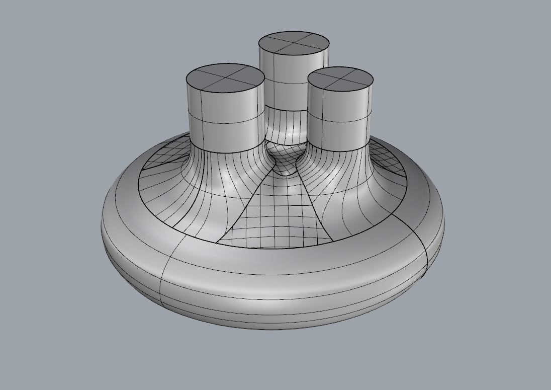
If you look closer, the real cylinders are too close together, and your way doesn’t create the model that I need unfortunately. It’s a little more complex than that, the center blend between the cylinders is higher than the base. I tried it one way and uploaded the 3DM file called HELP, and hoped someone can show me how to finish it. I uploaded a screenshot of that model.
Also this is a different model then my other posts, and a slightly different approach that I was hoping someone could show me how to finish it by opening my .3dm file. I used an old photo from another post just to show what this model is kind of supposed to look like, but they are different in many ways. The cylinders in the photo are centered, yet what I really need, is a model where the cylinders are off centered exactly like my 3dm file.
Hi @sh1tara
Here’s one example made with xNURBS - Looks OK clean, but not sure if this is what you are after?
HTH, Jakob
HELP xNURBS.3dm (1.3 MB)

Hi again @sh1tara
Here’s a version with G2 matches instead of G1 (Curvature matched instead of tangent) and it looks a lot better - especially if you try and turn zebra stripes for the whole thing. Your surfaces were all G1 (from the main shape to the top surfaces and from the top surfaces to the cylinders) and with G2 you just get a much nicer surface flow.
HTH, Jakob
HELP xNURBS G2.3dm (5.7 MB)


Jakob!! Thank you so much!! I want to open your files but I have Rhino 5 and its telling me that I can not open your files because they were saved from a newer version. Are you able to save them as a Rhino 5??
Blastered… Would these steps be variable blend surface, ???(not sure what is next) somehow you trimmed them at their intersection, pipe from curve, trim, blend surface, match surface???
Hi @sh1tara
Sorry - I didn’t see your message before, but here it is in V5-format:
HELP xNURBS G2 V5.3dm (7.5 MB)
-Jakob
Edit: BTW, if you want a better chance of people seeing your reply, it’s a good idea to use @[username] - this way he/she will be notified (if the user hasn’t turned notofications off).
@Normand Hey!! THANK YOU SOOO MUCH!!! So can you tell me how you finished my model??? Which steps?
Hi @sh1tara
First thing I did was to Untrim (with KeepUntrimObjects=Yes) the three blend surfaces (from the cylinders to the main shape) so that I could use MatchSrf to match the edges to the cylinders and the edge of main shape - using curvature instead of tangency - for a better flow. After that I used the trim curves from the Untrim operation to re-trim the surfaces. The three-legged “fill surface” is made using a plugin called xNURBS (which is currently Rhino 6 only - sorry). In this case it’s simply a matter of selecting all the edges, setting it to G2 (aka curvature) continuity, adjusting a couple of sliders and clicking OK. xNURBS is a fairly cheap (currently 295$) plugin that is really great at patching these kind of complex multi-sided holes. It can also be used to make more complete surface flows and objects. See www.xnurbs.com for more info. If I had to do it without xNURBS, I would probably go along the lines of @Blastered, using BlendSrf and Patch. I’ll try and make a quick example of a “no plugins” version later.
-Jakob
Hi again @sh1tara
Heres a quick “networksrf and patch” solution for V5. Matchsrf used to make the transition surfaces G2 and the I used SplitEdge to divide the edges and Blend (with the Edge option) to make curves going from edge to edge (the curves are in the file). The main blends are made using NetworkSrf (again, with curvature continuity) and then the mid section is made using patch. The solution is not perfect and I’m sure it could be refined, if one was to spend a little more time on it 
HELP networksrf and patch V5.3dm (2.3 MB)
HTH, Jakob
hello @sh1tara
First image is a solid.
Second one is a blend or fillet edge without any variable.
Third image shows the intersections between those blend surfaces that will be used to pipe but you need to adjust the ends of them to go straight
Fourth, is pipe
Fifth, trimming
sixth is a blend surface
there is a seventh step that is not seen here which is filling the middle of the blends.
Hi @Normand,
I know it has been a few months, but I really would like to figure out how you made this model using your “Networksrf and patch” solution for V5, but I can not replicate what you did. I am trying and I am not getting it. Are you able to give me a step by step with images, or possibly a video of your steps?? I am crying, i can’t figure it out 
Hi @Blastered,
On the third image, How did you get the intersections between those blend surfaces that will be used to pipe??
Hi @sh1tara
As I mentioned, the previous version of the patch was made with XNURBS in V6 and just saved as V5. Here’s the same method in V6 but without XNURBS - should work more or less the same in V5. Blendsrf between the main body and “towers”, trim away the majority of the blend, use patch to fill in the gap. XNURBS gives you more control of the way the patch behaves, but I think the result is OK. 3dm attached and GIF (50mb) download link at the bottom.
HTH, Jakob
HELP_V5_jn.3dm (488.8 KB)
@sh1tara select only 2 of those blend surfaces and type “intersect” and enter those blend surfaces’ intersection should be a little messed up at the end so delete a couple of its control point (by pressing F10 you can turn on the selected curves control points) then extent it and pipe
@Normand THANK YOU and thank you for the video!! After many painful hours I think I finally got it!! I was wondering though, how do you get your final model to have less lines?? Mine is top pic, yours is bottom.
Hi @sh1tara
I’ve just turned off the isocurves. Just go to the Properties panel with any given (or all) objects selected and de-select the “Show surface isocurve” button. You can also go to Rhino Options>General and de-select “Show surface isocurves”, if you want new geometries to not show the isocurves (they can always be turned on later, if needed). It’s a personal preference, I guess. I’ve always hated having the isocurves on, but know plenty of users who have them on at all times.
HTH, Jakob