Guitar Recurve Help

Hey gents and gals -

I’m hoping someone can help me out. I’m attempting to recreate a recurve for an arched-back guitar.
I’ve created the outline of the guitar and then offset inward, 1/2" to create a ‘zero’ point. Next, I’ve ran a line down the centre as a guide and then every two inches created a polyline with the height matching approximately the measurements I took from a real guitar.

Next, I used the ‘interpolate points’ from the curve menu to join all points together.

Where I’m running into issues is in ‘smoothing’ out the curve. To establish my ‘real world’ curves, I took a curve gauge (similar to what’s used to copy molding profiles) to the guitar and then drew the curves on paper. You can see in the paper version the curve is fairly smooth but when I use the ‘points on’ or ‘edit points on’ (not sure what the difference is between these functions), when I adjust the points, the curve leaves the ends of the vertical guides I’ve drawn.

I have four curves running across the guitar as well through the vertical centreline that I’ll need to add and then somehow surface the whole thing, but getting this initial curve dialled in is square one. My ultimate goal is to CNC out a ‘dish’ in MDF to create a press to form-fit veneers to hold this shape.

I appreciate any help!
Thanks,
Mike

HI Mike,

Using the measured points from your arching template to generate an interpolate curve will constrain the curve to these points. You can analyze the curve using Analyze/Curve/Curvature Graph On. If you want to edit the curve you can use the tools in Curve/Curve Edit Tools. This will necessarily pull the curve away from your template points but can help make the resulting curve smoother.

Moving the control points manually is often risky - if the point count is not extremely low you can get local distortions fast, so it is generally better to use the tools in the Curve Edit menu until you are close. If you want to control the curve directly try using SoftEditCrv. It will let you move the curve around manually while maintaining a falloff distance to keep things smoother.

Once you have the centerline curve in place the perpendicular cross sections will need to intersect it. You can use interpolate curves again and Sweep2 to keep the surface on the curves. I use this as a starting point then run Contour through the surface and continue to refine the curves until I finish with NetworkSrf. Finally you need to consider the co-planar surface where the arched back will meet the sides/lining. You can use SetPt to help keep this flat without local distortion.

We have corresponded on this subject already in personal message-if you can post the files here I think you can get better assistance, or if you prefer you can send them to me offline and I’ll do my best.

1 Like

facing similar issue.
i guess above thread works.
i would like to know the review if you have tried that @mbhwhitney
Thank you in advance

1 Like

Hi,

I’m just going to toss this out as an alternative option.

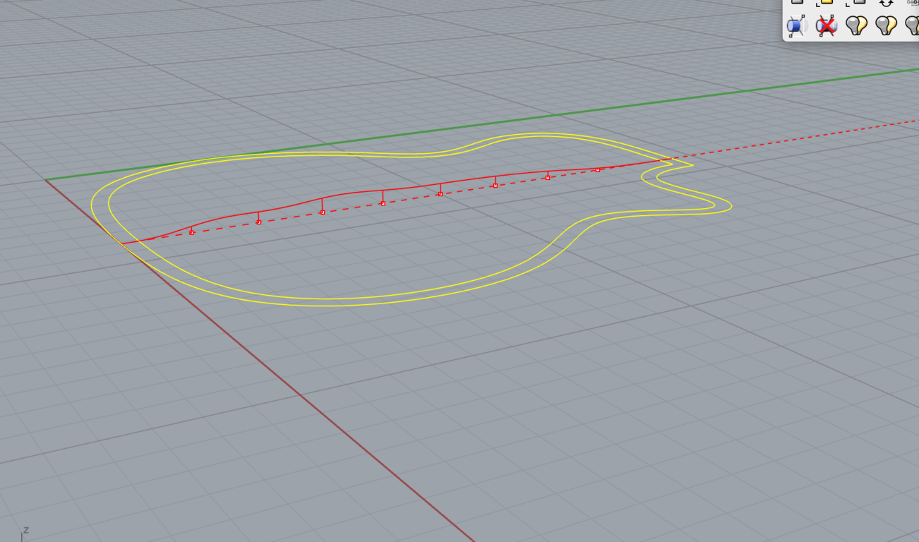
I’ve done a fair amount of curve fitting and have often taken depth measurements at specific distances to plot out the control points for a set of curves—like what you’re doing here.

My first attempts of doing this were usually to level off a straight reference edge (typically one that covers the full distance of the contour—so I never have to reposition anything)… and then measure down from there for the depth readings, using vernier calipers.

This approach can be pretty accurate… but there’s room for improvement here since those reference points ultimately end up exerting an influence over the missing points that were never measured in the first place.

Resolution is of course the key here, and the closer together the points are… the more faithful the representation of the curve will be.

Generally speaking these days—and I say this begrudgingly (because I really like to find any reason at all to pull out any of my fancy and expensive measuring tools that I bought as a younger guy)—but, I don’t bother doing it this way anymore.

One can get better results by simply tracing the full contour of the profile onto any semi rigid surface that can easily be written on, and cut. Two of my favorites are 1/8 (or 1/16 MDF panel)… or even a suitably stiff bond paper (like whats often used in watercolor drawing books).

It’s not that hard to scribe and carefully cut to a scribe line. and from there You can photograph the contour and import that image into Rhino and start trace over the true outlines in that photograph if you wanted to.

What few mistakes are made can easily be fixed by remembering to always cut on the outside of the scribe line… and sand back to it using the grade of sandpaper to control how much you take off. It’s pretty hard to screw up a template with or 220 grit… and likewise you don’t have to sand too much if your using 60 and 80 grits.

Scissors and an x-acto knife take care of the paper templates (…and paper of the right weight can be sanded too, it just needs a little backing board, or finesse by sanding in-line along the papers edge—and not strongly across it, to point where you start to bend and fold it).

But the shortcut here is that don’t even have to cut the material you trace your line on… That’s only needed if your making a template which you want to do work off of.

For just importing an image into Rhino. Having the accurate scribe line is all you really need.


Below is an example of a panel sitting on two spacer blocks showing that you don’t even have to be in direct contact with the surface of the contours your looking to copy.

With a little extra work and preparation those block can be rigged so that they form L-Brackets and can hold the scribe panel in the position you want to use it in. Nothing fancy needs to be done here.

The only rule is that you want all of your scribe line to fit on the panel… and you don’t want anything to shift or move while your making your tracing (or scribe).


My last comment here is simply going to be a small apology… or justification perhaps. The thought did occur to me early on that if your talented enough to be making instruments… you probably don’t need to read my rambling about how to scribe a template.

My entire comment could have been reduced down to…

Hey, Mike why don’t you just scribe a template… and trace over it in Rhino.

and I’m sure you’d know what I was talking about. But others might not… so for better or worse I over explained things to cover the basic ideas for those who might not already know. This could be a mistake, hence my apology, in case this happen to rub you the wrong way.

Take Care, and good luck with the project,

Jim

1 Like

When looking to create smooth curves the cardinal rule is : as few points as possible.

Each point you use has an effect on the “smoothness” of the curve. The smoothest curve would be an arc. If it turns out that your target curve doesn’t have the uniform curvature of an arc, then add a control point in the middle and see how close you can come by moving it perpendicular to the curve. If that doesn’t do it, move it closer to one end and add another the same distance from the other end and experiment with the two. and so on. Each point you add adds more potential for “waviness”. One more consideration: if your target curve is symmetrical about it’s center and you’d like to reproduce the symmetry first build only one half and then mirror it for the other half.

2 Likes

I would not disagree with this at all.

My suggestion for a higher resolution should only apply to inputing the curves which are trying to be matched.

Once inside of Rhino the better goal is to use as few points as possible, for all of the reasons you mention.

I just think that having the more accurate tracing will allow for a better choice for finding where those point should go… as opposed to basing everything off a 2" point sample that doesn’t represent some subtleties in between.

Whatever compromises are settled upon for limiting point counts can be made by comparing the differences between the two.


I was thinking about the symmetry as well… and how half the curve could be mirrored. But I’m not sure if there is symmetry along the neck line axis.

I think the symmetry is present going across the strings (perpendicular to them) for sure. But in-line with them, maybe not. I don’t have one nearby to look at… but I don’t think the body tends to taper back down, and thin out, at the area where the neck gets attached. That’s probably the full thickness if only for structural reasons.

1 Like

Hi Araham -
Thanks for your reply.

Using the measured points from your arching template to generate an interpolate curve will constrain the curve to these points.

I could be mistaken, but is this not what I want to do? I think (and I could be completely mistaken) that I want the curve to hit those points so as to stay true to my measurements but then even out the curve some how.

If you want to edit the curve you can use the tools in Curve/Curve Edit Tools. This will necessarily pull the curve away from your template points but can help make the resulting curve smoother.

Is there a tool from this menu that you would recommend, specifically?

If you want to control the curve directly try using SoftEditCrv. It will let you move the curve around manually while maintaining a falloff distance to keep things smoother.

I’ve not yet explored this tool but will look into it.

As a note, I just chose a spread of 2" because it seemed to divide up the curve nicely for reference points. I can certainly eliminate some of these lines for fewer points, as you say, and try making the curve again.

Finally you need to consider the co-planar surface where the arched back will meet the sides/lining. You can use SetPt to help keep this flat without local distortion.

I recall you mentioning this in your previous note and thought I had my head wrapped around it… being ‘green’, I’m not completely sure what you mean / how to accomplish this. I can certainly post the file here or email it to you. I’d love to learn how you’d approach this / or even better, see a video of how you would work this curve.

Thank you for your help - I’ll post this shortly, below.

How accurately are the measured points? How close to the measured points does the curve need to be. (Any closer the accuracy measurement is meaningless.) Create points at the ends of your vertical lines. You can then use PointDeviation to check the deviation of the curve from the points. Also use the curvature comb (CurvatureGraph to turn it on) to check the smoothness of the curve.

PointsOn turns on the control points which are generally not on the curve. When a control point is moved the change to curve is smooth and without oscillations. For multi-span curves (number of control points greater than degree of curve + 1) each control point affects only a portion of the curve. Edit points are on the curve and the curve moves so that they stay on the curve. Move on edit point and the curve continues to go through all the edit points. The drawback to editing curves using edit points is the entire length of the curve is affected when you move a single edit point, and moving edit points tends to cause oscillations in the curve.

To obtain a smooth curve which is close enough to a set of points frequently requires some manual editing of control points. Initial attempts can be very frustrating but with practice it becomes
much easier. Very similar to a lost of woodworking, particularly using hand tools. Use Rebuild to experiment with different numbers of control points. More control points allows a more accurate fit to the input points but is more difficult to make smooth. Curves with fewer control points are easier to smooth but are limited in how accurately they can fit the input points.

1 Like

Hey Jim :slight_smile: -
Not at all my friend. I appreciate the thorough explanation as well as the succinct one. I like detail!

The scribing method you explain makes complete sense.The problem I now face is that a) It didn’t occur to me to approach it in this way; and, b) I only had the instrument for a short period of time - point being, I don’t have it anymore so have to rely on the five lines I took with the gauge (one vertical running longitudinally and four lines intersecting, running laterally).

I’ll keep experimenting here and appreciate all the knowledge / insight. I think I need to ‘see it’ being done; unfortunately, being fairly new to Rhino, I just lack the tool knowledge insofar as what does what and what can be accomplished. I can’t help but think there must be a way to keep my target points in place while smoothing out my curve, even if it means reducing my targets to fewer control points…

Cheers again!

Thanks AIW -
I’ll attempt to play with the control points as you’ve outlined. The lateral lines will be symmetrical, so I’ll mirror my points as you say - thanks for the tip. The vertical centreline (as I posted) is not, so I’ll have to work that in its entirety. Looks like too many control points are the culprit (and again, I just chose a 2" spread, arbitrarily)… I’ll have to play with this when I’m back later today.

Hey David -

How accurately are the measured points? How close to the measured points does the curve need to be.

This is a good question. As accurate as I tried to be with my curve gauge, I realize that when I attempted to put in the lateral curves, the intersection points did not line up with the points on my centreline. I guess my point is that getting my dish (end goal) ‘close’ is okay with me. I don’t want to deviate too much, but 1/16" +/- is fine.

I’m going to re-read your notes on manipulating the curves when I’m in front of my project later today. Thank you for your insights.

Hey gents -
I’m uploading the file if anyone is interested in taking a look. It would be great to have a ‘visual’ / short video to see how one might approach this. There’s a bit of a mess in my other layers as I’ve been trying different things but my main centre line, outline, offset and ‘curve profile’ layers are a close ‘rough’ work. ‘Show objects’ will reveal where I’m at so far. You can see things look a bit ‘wobbly’ at this point :). Also, it’s apparent that my intersecting lines don’t hit the same targets as my vertical centreline… something I need to play with.

Lastly, I realize that I need to invert this whole thing as my dish should go downward vs upward (an oversight) but I imagine there’s a simple operation to do this on the other end once surfaced?

Back_Recurve.3dm (2.6 MB)

Hi Mike,

Are you using Rhino 5? While it won’t help to say this, in Rhino 6 _CurveThruPt gave me a much smoother line than your red one - probably good enough to use. The only real problem is your offset line which introduces a slight reverse curve between itself and the edge. A minute vertical shift should lose that.

But your various curves don’t marry up, so whatever else you do, you are going to have to resolve the discrepancies before you can build a surface.

Regards
Jeremy

1 Like

I might not fully understand what you are trying to create but I would think the Patch command could make a surface that is within 1/16" of your curves

patch.3dm (117.9 KB)

BTW, your outer curve has a bunch of stacked control points. You may want to fix that if you are going to use the curve to make surfaces.

You can use Rotate3d about your center line to do that

1 Like

To preserve the position of the cutaway you need to use mirror on the XY axes rather than rotate…

1 Like

This is what the “snap” tools are for. At the bottom of the viewports if you are using the default toolbar setup.

What you are trying to do is usually referred to as “reverse engineering”. i.e.: taking measurements from an existing object and trying to model it accurately.

There’s an art and a lot of judgement that goes into the process, which, when you first think about it, isn’t obvious. Here’s why:

CAD tools are very accurate modeling tools. Far more accurate than manufacturing and physical measuring tools. They also have visualization aids that far surpass the real world in disclosing details and imperfections. When you start with real measurements you need to regard them as suggestions, not something to duplicate.

You need to be able to make some judgements and assumptions about what the initial designer intended (or what you’d like based on the original). Most designers and craftsmen have some ideal concept they’d like to implement and if you can make a good guess about what that is you can then use the precision of the CAD tool to get a lot closer to the ideal than trying to duplicate some wavy line or surface represented by a bunch of points with random variations from the ideal taken by a (relatively) imprecise measuring system by an imprecise operator.

When I talk about “visualization aids that far surpass the real world” I mean things like Curvature Graph, Zebra map and Environment Map, etc. They will show you imperfections in curves and surfaces that you can’t ordinarily see. Although there are some who post here who have a good enough eye that they can detect quite a bit, especially if they are looking at a real 3d object under the proper lighting conditions.

So start from the suggested shape of a real object, but design from “scratch” guided by it.
Don’t try to duplicate every point or even the small details of a template curve pulled from the object. This advice also applies when working from a blueprint or even from a CAD model supplied by an unfamiliar source.

On that last point, although it might be a little off-topic: this forum is filled with posts that refer to embarrassingly sloppy CAD work from outside data sources and the effort it takes to clean them up. Sometimes in this case starting over from scratch is the ONLY recourse.

1 Like

This is REALLY important and goes to my earlier point about “as few points a possible”. It’s not just that they are superfluous. They actually mess things up in a big way for a lot of subsequent operations.

1 Like

Start by rebuilding and properly aligning all the curves. You want degree 5, 6 point curves. Then you can build surfaces from Edge curves. You want bezier surfaces that can be easily point edited and matched.

4 Likes

Thanks Jeremy.

I’m using Rhino 5 on a Mac.
Definitely - I hear you RE needing to marry up my intersecting points. I wanted to hammer out how to smooth this curve first and foremost, and then work on tweaking the other curves.