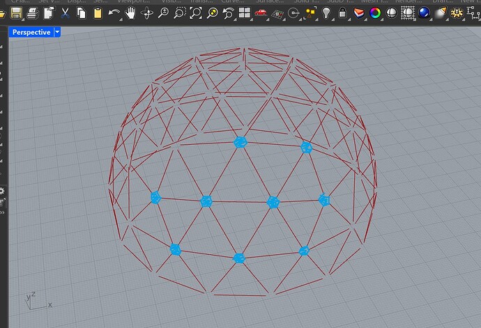
Hello, I’m trying to make several custom connectors for a geodesic dome. I tried Boundary Volume, but it didn’t work. I also tried this approach: Geodesic Dome - Nodes problem , but nothing works. Does anyone know how I can solve this problem?
What are these connectors supposed to look like?
Maybe you can provide a small example without Plugins, so we can check without installing. Regards, Eef
Thank you, Rajeev. Your solution is very helpful—it’s not exactly what I was looking for in this case, but I can definitely see it being useful for other parts of the project.
create 1 connectbar (truss) as independent object. Simply on the xy plane.
When doen. At all connecting points, create a plane.
to do so, I would use the centre of your dome. Line to the connecting point.
perp frame at the end (t=1)
Use orient to get your connectbar to all connecting points.
When you say you want “custom” connectors, what do you mean? I see in your screenshot that you have a regular geodesic dome, which needs I think 2 different types of connectors. What prevents you from modelling those?
Or do you actually want to change the shape of the dome and have the connectors adapt?
I remember there was a long thread on the old Grasshopper forum where someone made this. Not for a geodesic dome, but just for custom connectors to create furniture, but I cannot find it at the moment.
Keep in mind that you have different topologies for the connectors. Pentagons, hexagons and all connectors on the perimeter…
The approach with one single connector would only work if all struts had the same length and even then you have five and six struts joining at the nodes.
What size is this going to be built in?
“Custom”, because some points have 5 struds, others have 6… for this reason i put custom.
For now, measuring 1.20m in diameter, it will be displayed at an event at my university. But later, it will be built on a full scale, about 2.5 times larger.
So first you basically build a model which could be 3D printed in multiple pieces?
Yes. The big one also will build wiht 3D printed pieces.
The question is where you will split the parts so they’re small enough to print.
The model might be split within the struts and the real build could be printed nodes and struts out of readily available material / tubes.
I understand. But initially, the intention is to print as much as possible (all parts), even if that means splitting the parts for later assembly. There will be room for non-printed elements, perhaps a hybrid approach, but as a contingency measure.
Hello, first of all, thank you for your attention. I don’t know what’s happening, but when I open the file, it doesn’t work. Maybe a file is frozen or corrupted. Can you resend it?
Ok. For me the definition runs when I change the curve node.
But your approach doesn’t work for all of us. I’m still researching and trying to find a solution. Tks ![]()
yes u need to increase the length then use region and can select by largest area u get what u want


