Hey there,
I need some help with this Form. I try to make the cylinder flow into the other surface…
I attached the file and a sketch.


Forum_Frage.3dm (689.4 KB)
I really appreciate any help on this!
Thanks
-Paul
Hey there,
I need some help with this Form. I try to make the cylinder flow into the other surface…
I attached the file and a sketch.
Forum_Frage.3dm (689.4 KB)
I really appreciate any help on this!
Thanks
-Paul
Hi Paul - is this what we’re shooting for?


-Pascal
Yes, they are supposed to be filleted too. That looks quite good. The radius on the top should be larger, which was where the problems started. It should be about 10mm.
Thanks!
Basically that is the right way. However, the sharp edges at the top should be smooth. That is where I didn’t find a solution. I tried to use the surfaces from the fillet and trim them, but they never intersected. So I never got to your solution.
Thanks!
I think I have something in mind. I will try it and then see if it works.
-Paul
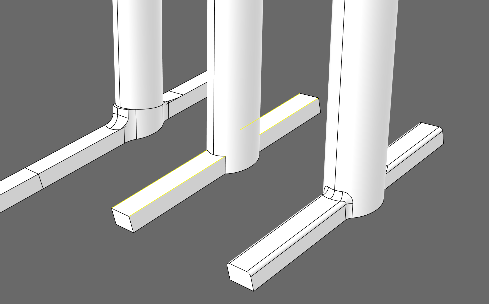
There’s a small problem in this corner. The two fillets with radius 10 and 4 mm in my example do not end in a clean corner. It causes the sharp edge fillet to fail. One way to fix it is to subtract a sphere from the object, create the edge fillet and close the hole with a patch.
Forum_Frage.3dm (1.2 MB)
In the end I used fillets on some corners and Blendsrf to connect the 2 parts. It gave a better surface and I had less problems with it. It won’t go into production soon, for now it will suffice. Thanks to both of you @martinsiegrist @pascal
It was very helpful!
Best regards
-Paul
fillet_2022-11_mcneel_01_tp.3dm (103.0 KB)
… i love those fillet-challenges…
it s always nice to do a sphere-based only fillets - like above solution.
but many times our (or at least my) eyes and brain are more convinced by solutions that are beyond just using _filletEdge. Maybe this is more a model-maker perspective, trying to do it in a graphical way, like using filler and sandpaper in the workshop?
kind regards - tom
This looks like a nice exercise that could be done in so many different ways. ![]()
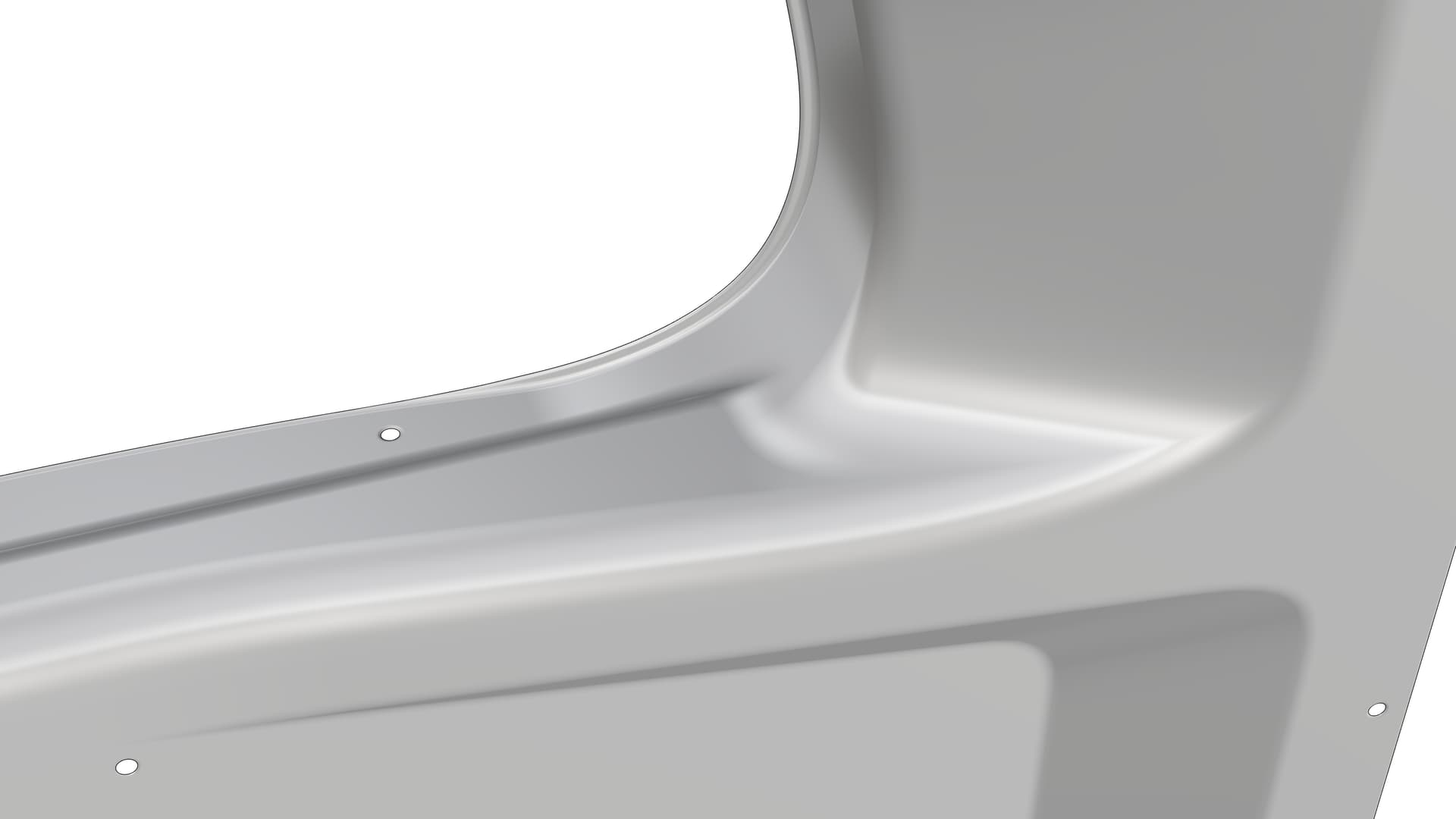
I often do manual filleting job with the VariableBlendSrf tool and I love trying to figure out unortodox solutions outside the typical round fillets. The two videos below show some techniques applied to a geometry where Rhino’s fillet tools would fail to deliver visually pleasing results with ball fillets only. Some areas of the model were improved after the video recording, so they don’t represent the final design.


Hey Tom,
I often think in that way too. However, I tend to think too complicated… The solution presented by other members sometimes makes me think I don’t understand 3dmodeling… Thanks for the advice!
I’ll just keep practicing.
-Paul
You refer to the rollingball option?
Yes, it’s usable in areas that should follow round pipes or similar shapes that need to be CNC-milled with a ball tool, but they usually don’t look good when covered with a shiny paint.
I have a question: would it have been possible to replace the two patches (in the red-marked area) with one (4-sided) surface patch instead?
I do assume that there are good reasons for ending up with the existing trimmed patches due to gradual design steps, but from a “distant spectators perspective” the question is if they perhaps could be replaced after the nearest fillet has been put in place.
In any case, very impressing modelling and good looking final result!
//Rolf
The final design of this particular part is slightly different than the one showed in the videos. The blend surface you see above the 4-sided surface you drew over my model is no longer used as it was replaced by a large blend surface to enhance the looks.
There were two reasons why I opted to use a traditional sideways radius fillet rather than replacing it and a portion of the flat horizontal surface with a 4-sided patch as showed in your image:
The CNC-milling of this particular part had to be done with a basic 3-axis CNC-milling machine while the part is being flipped to 90 degrees on the milling table (in comparison to its position on the chassis). The 4-sided surface you propose would produce a negative draft angle which is not good for use with a 3-axis CNC-machines. This is why the surface had to be kept vertical on the milling table, or sideways when viewed on the car. I explain that in more detail in the latest post here:
Aeromaster LMP - #33 by Rhino_Bulgaria
From a pure design perspective, the sideways fillet is a great way to force the light reflections follow the same direction. An alternative rotated 4-sided patch could never deliver perfectly straight, sideways light reflections. This interior panel is designed to be produced either from carbon-fobre composite with a highly reflective coating or a matte fibreglass. The reflective coating easily shows the advantage of using a proper straight fillet over a freeform patch. But the main reason is point #1.