I was attempting to extract the outer surface from this mesh but couldn’t find a perfect way to. I’ve tried:
Drape: it doesn’t collect the shape of the other side since this is a cylindrical shape.
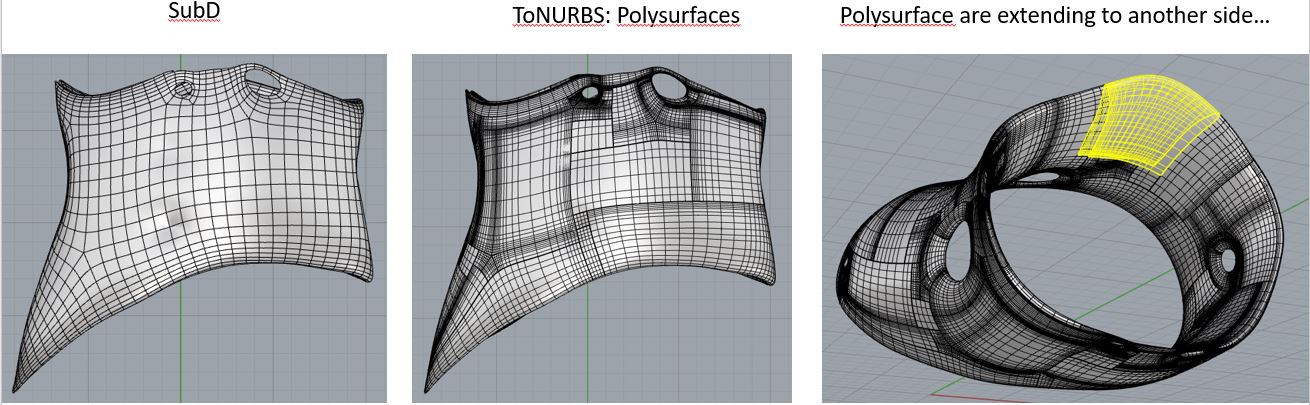
Shrinkwrap: it results in a mesh (I’m looking for a surface) and doesn’t copy the hole detail on the mesh.
Manually: turned the mesh to NURBS and manually revomed the extra faces when I was very desperate, but it end up in many small surfaces instead of a intact one. (I need this ONE surface to do diamond panels later).
Does anyone know if there’s a perfect way to do it? I would really appreciate it!
As i suggested before , try to create section or draw curves and project them on the polysurface than use loft for example to create a surface
Try and use any tool can help you with your shape
Thank you Martin for the reply! here’re the files. In this file lays the model after topology. But if you need the file one step earlier (the surface- extrude-topology) I can provide it in the following thread.
This problem has cost me 2 weeks to figure out, and now thank you, it’s solved! However, the result is in mesh, i was looking for something like a full surface.
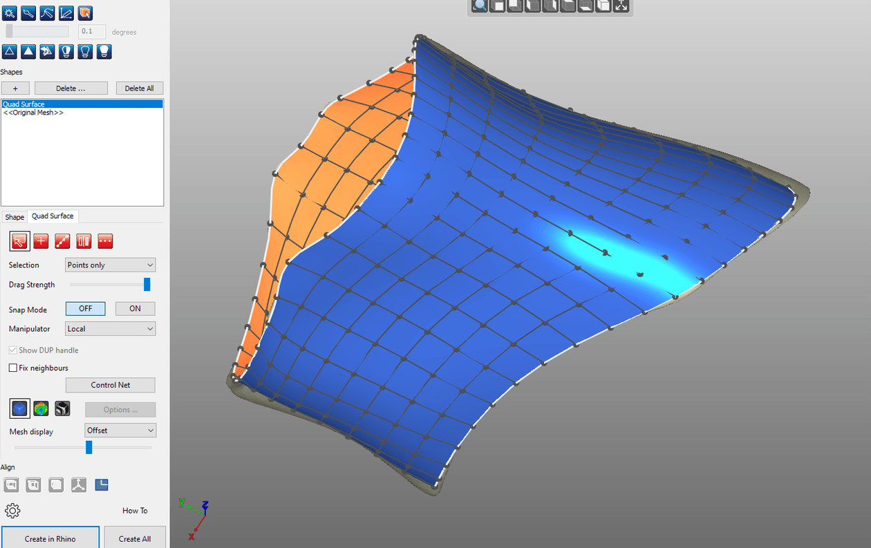
I found this mesh2Surface tool really handy, for anyone who’d deal with this kinds of problem a lot, purchasing a license in this software is definitely worthy!
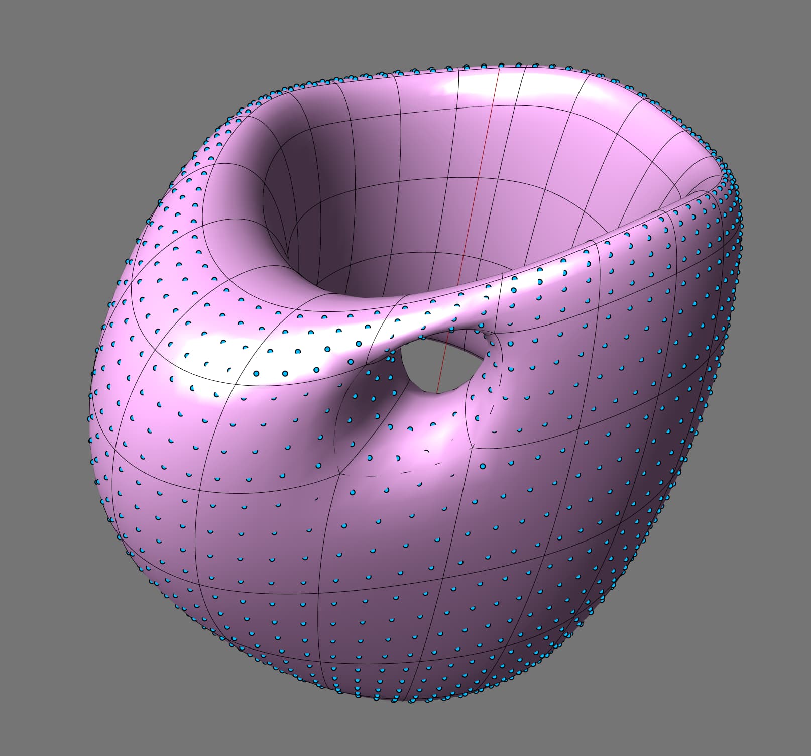
Here is a single nurbs surface created by a different approach. However, I created this without the holes to save time; I don’t know how important they are, or whether they are all deliberate, but I felt that it would be easier to get regular shapes by trimming a complete surface. Similarly, you didn’t specify how close a fit between the surface and the mesh you need, so this is a compromise between a simple, easily reshaped surface and one that is harder to modify but repeats some of the mesh irregularity.
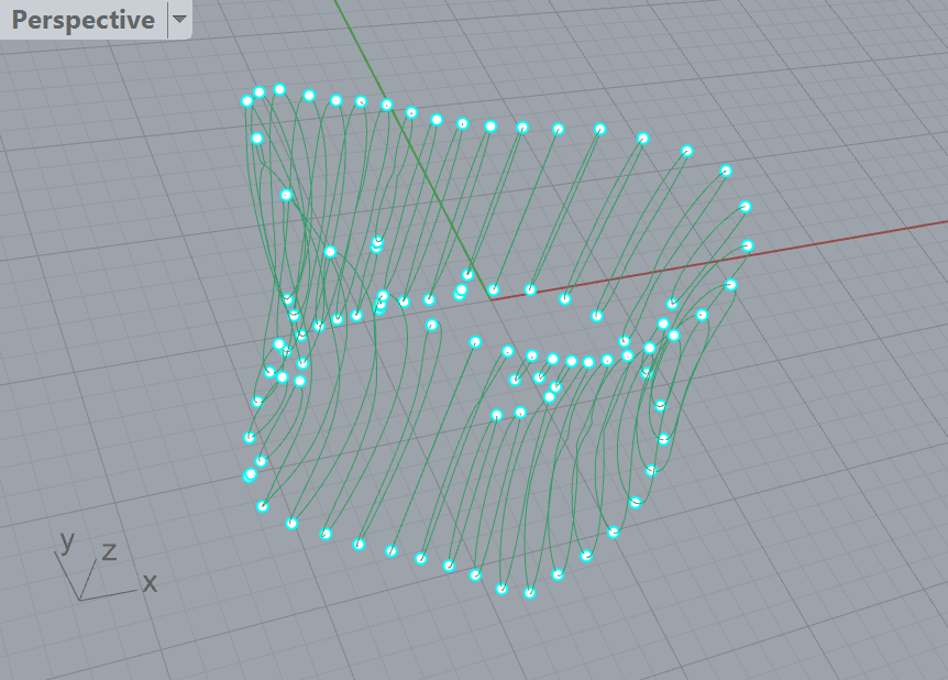
I chose to sample 36 sectional curves around the tube, then trim these using the curve maxima and minima to remove the inner parts. I blended the curves where the holes intervened, then rebuilt them to a consistent point count of 15 before lofting them to create the surface.
I used grasshopper to create the sample curves and the maxima and minima points, but the rest was done in Rhino.
Because the inner and outer meshes are not aligned, and because the rays are diverging, I think it is possible for an outer surface to be missed by all the rays extended from inner surfaces, the untouched ones account for the gaps in your result.
By shrinking the lines and culling any faces with no intersections, as @ErickVasquez did, you may instead end up with unwanted inner surfaces, but because the rays are converging that is less likely; in any event such floating surfaces will be less problematic.
Thank you a lot Jeremy! This is what I’m looking for.
However, would you be happy to show how did you do this in each step? When I open the file, I see the sectional curves, min and max points, but not exactly what you show in this picture (though you baked this geometry and left it in the file attached)
It would be great if you could explain the steps in between the grasshopper part and the final part. …Could you?
I dragged the mesh to be centred approximately on the origin, and rotated it so the tube was vertical, to make it easier to work radially.
I used grasshopper to generate 36 vertical planes around the z axis and create intersection curves with the mesh. Grasshopper also generates the highest and lowest points (maxima and minima) on each curve. I baked the curves and maxima and minima into three new layers.
Note: If the ultimate surface diverges too much from the mesh you can come back to this stage and increase the number of planes.
I copied the intersection curves to a new layer ready to trim away the unwanted inner parts (keeping the original set is a useful precaution against later mistakes!).
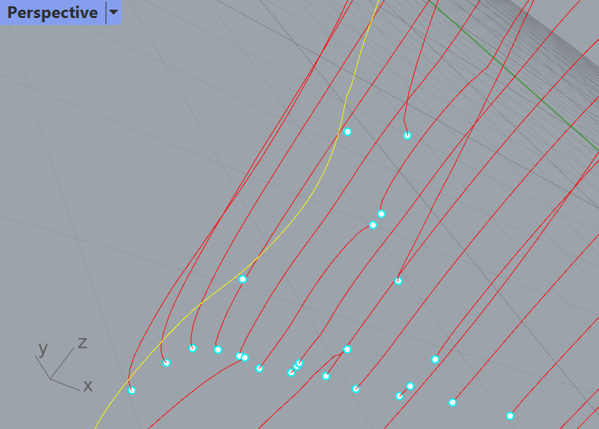
I selected all the maxima and minima to be the cutting objects for the trims and removed each of the inner parts of the intersections.
Next I removed evidence of the holes. I did this because if the holes are supposed to be regular I felt it would be better to boolean out precise cylinders later - as the mesh surfaces are large in relation to the holes they don’t represent them well. Where curves were interrupted by holes I split each of them with the point where they turned inward and deleted the ends, then used blend curve and join to fill the gaps. There’s a degree of trial and error about this.
Finally, I created a closed loft of the rebuilt curves.
You will want to compare the generated surface with the original mesh. If not sufficiently close you can tweak the rebuilt curves’ control points, use MoveUVN on the surface, go back and increase the number of planes, either uniformly or by adding planes strategically, and/or increase the number of points in the curves.