Controlling parameterisation in Flow Along Srf or GH

Hi there,

I may be asking something obvious but I’ve not managed to find anything in searches or on the forums for this:

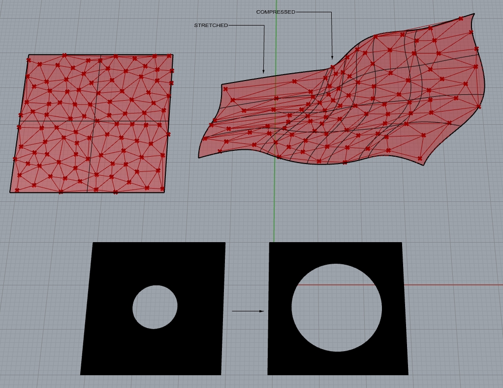
Essentially what I’m trying to do is map a selection of curves (delaunay mesh-ish) from the area between an outer square and inner circle, to the same area, but with a larger inner circle. In real life the pattern’s not that simple, and neither is the whole square-circle thing, and there are engineering tolerances…etc, but hopefully the image gives you the basic idea of what’s going on.

The problem I’m having is when I try to map from one surface to another it’s creating too much distortion (bowed edges along the straights of the square…etc.)

I’ve tried mapping the pattern from old to new surfaces in straight rhino with flow along srf, and in grasshopper with closest pt and eval srf (image attached).

I’m pretty sure the problem is, as illustrated on the sample surface (image attached), that the parameterisation of the surfaces is not all that even.

To even it out I’ve tried building both surfaces using exactly the same method, with the same number of control points in U and V, with the same distribution (which is even in XYZ cartesian space), on both starting and target surfaces (which I usually do for flow along srf anyway). Both flow along srf and the GH method I used (also in attached pic) still come out with quite a lot of distortion, though flow along srf seems a little less distorted so I guess it’s doing some form of rebuilding or reparameterisation within it.

My workaround so far (as rebuild makes it too different a form) has been to break up the surface into a few hundred smaller segments, all constructed in the same way and map them all (essentially kind of manually resampling it so the distortion within the segments is physically smaller), but this is a pretty inelegant way to do it, and still requires a fair bit of cleanup as it still creates some edges that don’t quite line up.

Apologies for the long post but in essence, if anyone knows how to do a flow along srf type thing but to actually even out the reperamaterisation, either by doing something with the definition, constructing the reference surfaces differently or even at a push some scripting (I have an extremely hazy grasp of python in rhino) that would be massively helpful.

Apologies also that I can’t post up actual images or files but unfortunately it’s one of those client confidentiality things on this project.

Thanks again to anyone with the patience to actually read all that!

Rup

Within the current Rhino core code rebuilding is pretty much the only way to fix this stretching, and even rebuild doesn’t get rid of it completely.

What we would need is some algorithm which generates a mapping function (along with its inverse) from S_{uv} to N_{uv} where S stands for the underlying nurbs surface and N for a smoothed out spacing. You could then choose to work in either space and project back and forth as you see fit.

This is a reasonably tractable problem --although still one you have to type up yourself-- when u and v are independent. However it becomes really useful once you can smoothly deform the space as a whole, rather than the coordinates individually. That way you could even repair swirls and whorls in the uv space.

There is some overlap here with texture unpacking and mapping, so maybe we already have most of the logic needed for this. @andy can you see a way in which such a mapping can be implemented for arbitrary nurbs surfaces using texture tools we already have?

Thanks David!

If there is something that can form a basis that’s pre-existing within texture mapping that would be brilliant!

Having thought a little about it, based on what you’ve said, and thinking of something which might work in this instance at least, based on the comparatively little I know, the first thing that springs to mind using methods I have some idea about would be something along the lines of this:

Get UV co-ordinates of relevant points on initial surface, generate isocurves for these, get lengths of isocurves and distances along those that the points sit. Divide lengths by distances to get a more regularised 0 to 1 value for the relative position of those points on the surface.

Then creating an effective ‘regularised UV grid’ on the target surface to map these to looks like the fun part! The only thing I can seem to think of for this is to use recursive division of isocurve lengths to get the equivalent co-ordinate positions on the second surface, but this again seems like a fairly clunky way of going about it.

Creating something which generates a regularised UV space for any given surface (and can then be used to translate to normal UV, I guess via closest pt or something similar) sounds like a much better idea, but I don’t have much of an idea of where to start. Is there by any chance some way you know of extracting the relative density of the UV space (I guess the result would be something like a gradient or a curve for U or V density vs. ‘real’ distance) along the U and V axes (compared to length along the axes), without having to use individual co-ordinates to sample it?

Thanks again for your reply and do let me know if I’m massively misunderstanding anything! Your help is much appreciated!

Rup

It is almost certainly going to involve a lot of sampling and iteration to build this mapping. I have a vague notion of where to start, but I can see this being a really complicated problem with lots of special cases that need handling.

Eventually, to make it really useful and also really complicated, this mapping could cover perhaps several adjacent faces in a polysurface and treat them as a single patch.

I’ll try to get some of the core geometry guys interested during the next weekly meeting, but this stuff often ends up on the long term pile unless you do it yourself.

Hi David,

OK that sounds great cheers! Yeah polysurfaces would be very nice, and also maddeningly complex as you say, and I can see it being interesting trying to get it to work across closed single surface boundaries too (e.g. matching up continuously on a sphere or torus etc…). If you do have any success if you could let me know that would be great! In the meantime I’ll see what I can do in my own very basic way and if I somehow manage to get anywhere I’ll put it up in this thread.

Thanks again!

Rup

I’m curious to hear if there’s something in the Rhino code base along the lines of what @DavidRutten was suggesting. David, would you have any papers to point to or a brief explanation of the sampling method you’re thinking of?

I’ve had to build my own parameter system in the past. But my surface was fairly rectangular and close to planar. I was able to rely on the edge curves for most of it. You can use the length along the edge curves to then evaluate the isocurve at that location. It’s certainly far from a universal approach but might be worth a shot as it’s fairly easy to implement.