Im completely new to rhino/ grasshopper and am trying to understand the programm and how it works. Currently im challenged with the task of designing a modell of an apartement complex. My first problem is, that i dont understand how i create a grid and then define the two different sets of columns as well as the outer elevator on an parametric grid, so that they are independet from another. Please view the sketch for an overview of the situation. Any advice would be very much appreaciatetd.
Merging your inputs to DeBrep means that you combined squares and points from two buildings. So you lost a data tree structure that will likely be useful later.
Better to do it this way. CullPt(Cull Duplicate Points) before creating vertical lines means you won’t have any duplicate lines. The data tree structure means you could have different lengths for the two structures. Instead of lines, you could have created square or round columns.
Hello everybody,
due to your kind help i was able to create the columns and storeys on the grid in grasshopper. I used extrudet Volumes to create the different components. Now i would like to integrate a feature which will allow me to vary the size of each created slab and simultaneously delete the columns if there is no connection between slab and column. Any idea how that could be achieved would be very muck appreciated.
P.S. Looks like you moved the buildings? Makes it harder to compare. And you prefer short columns on each floor to the long columns I used? No problem, but I’ll leave that to you. The point is to do all things parametrically, so you can change the number of floors, for example without modifying any code.
Thank you very much!
Ill stick to this thread from now on its easier and more overseeable, youre right.
If i understand your solutiuon right you are copying one slab to create the upper floors.
The idea to create them indivdually came from the problem that i need to vary each slab in its size and then programm a function to delete the column there. My english isnt that great so please take a look at the sketch to understand the task much better.
There is always a way to do things parametrically - usually several ways. I don’t understand your sketch, sorry, and don’t see a big difference in the slabs between your model and mine, in size or position. But my advice is general, you’ll have to resolve the details.
Cutting holes for the columns is easy, It can be done before the extrusion (faster?) or after (SDiff is SLOW!). I don’t see any effort to do that in your model?
P.S. Here is a model the cuts holes for the columns before extrusion, without SDiff. It also treats the first floor differently - no holes. But I’m messing with details, that’s your job!
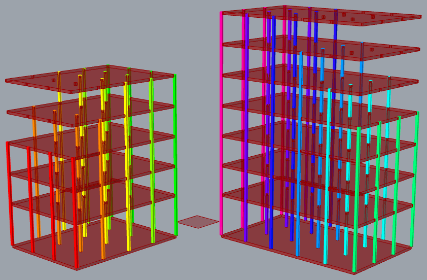
I can’t help thinking about this… and started to make changes to approach this problem parametrically by partitioning the grid points by four - and sorting the points inside the Grid Region cluster. Then realized that it works for one building but not the other so I added a ‘Pyx’ output with the points sorted first by Y, then by X. And got this (ignore column heights for the moment):
Promising, eh? But the next phase of adjusting column heights in a step-wise fashion immediately gets complicated, in part because these two buildings are rotated 90 degrees from each other and the Grid Region cluster has no provision for that. Consequently, the grid basis for this project needs to change somehow.
P.S. I enjoy this sort of thing. Frankly though, I think it’s very advanced GH code and data tree management so I am dubious about how much there is for a beginner to learn from it. I made more changes to the Grid Region cluster and got the columns correct. They seem to behave as expected when the number of floors is changed and/or the grid and building size is expanded.
YES! This looks exactly like what i want to achieve!
It is really complicated so i cant thank you enough for your effort!
Im trying hard to understand what happens in your solution. Im not really used to think the “Grasshopper Way” so im trying to deconstruct the steps you made to understand the process.
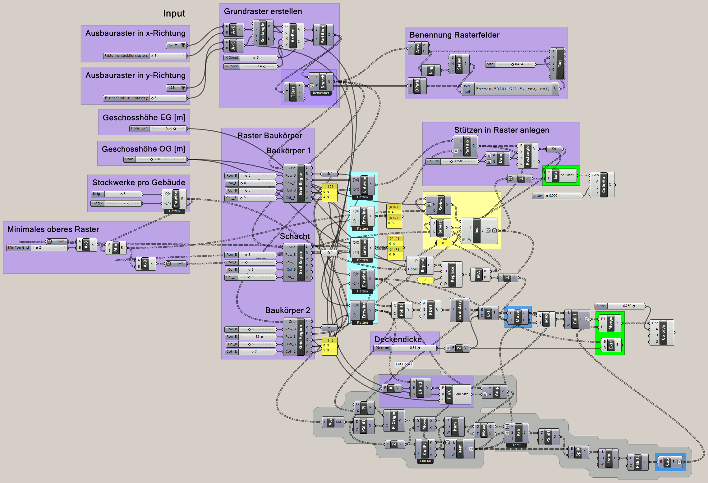
Perhaps the most important principle of “The Grasshopper Way” is that all significant inputs are parameters that can be changed while the model behaves in predictable ways. In my 2nd reply, I had sliders for overall grid dimensions and defining a Grid Region for each building. You replaced sliders with “hard coded” values in text panels that are not so easy to change, which is important to make sure the model remains fully parametric. I restored the sliders.
On the other hand, you departed from grid squares to grid rectangles, adding parameters that allow the grid to be defined differently. This caused me some grief in knowing which dimension to use when cutting off the top floor slabs.
As I said, there was little thought given to orientation of the buildings initially, but that became important when the concept of stepped top floors was added later. In the zeal to get code working, it’s easy to ignore parameters, as I did when partitioning grid points by ‘4’ because both buildings had four columns in one direction. I fixed that now but can think of at least one other case of “hard coding” buried in this code; two grid sections are left on the top floors - not a parameter!
I’ve noticed two anomalies that I haven’t fixed yet. When you change ‘Row_B’ for the first building from ‘2’ to ‘4’ or more, its orientation changes from X to Y (good!) but floors on the second building are wrong (bad!). There should be no mix-up between the two.
Also, when ‘Row_B’ exceeds ‘5’ (the number of floors), things get wacky with negative column lengths instead of adjusting that hidden parameter of “two grid sections are left on the top floors”, which would be the logical thing. This problem seems easier to fix than the mix-up between buildings.
I added a section on the left, “Minimales oberes Raster” (Minimum top grid) to set the minimum number of sections on the top floor. Everything else seems to follow correctly, as long as you stay within the bounds of the overall grid.
I’m not so sure that automagically swapping X for Y alignment is a good idea?
P.S. Two things:
The grid labels are broken. To fix them, enable preview in the “Benennung Rasterfelder” group, then ‘Simplify’ the Partition output in the “Grundraster erstellen” group.
The slowest part of this model is the RDiff component for cutting column holes in the floor slabs, which aren’t really visible anyway. You can disable it and connect the Entwine ‘R’ output directly to the Extrude input. Way faster!!
Internal to the Grid Region cluster, I added simple ‘Grid Bounds’ checking (yellow group) that prevents the row and column parameters from exceeding the grid limits. BINGO!