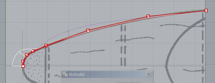
This is an overhead view of the nose of an aircraft fuselage. Probably the original plan was drawn using a parabola as a guide. In Rhino, I traced the curve using Interpolate curve, starting with several points pinned to the vertical line across the nose. The idea is to maintain tangency.
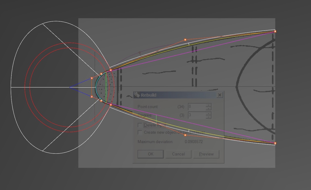
It took 34 points to draw the half-fuselage curve. I am now trying to rebuild it using maybe 8 to 12 points.
When I took level I, I must have looked out the window when the topic of rebuilding came up. Never quite sure how to proceed. The basic idea is to keep the shape of the 34-point curve while reducing the number of control points to a necessary minimum. But how, exactly?
The little barbell marker, for example. How am I supposed to use that?
Do we have a video on the subject of rebuilding?
Note that the rebuilt curve shown has lost all tangency at the fuselage centerline, so part of the problem is to restore it.
Hi Michael - I would draw this from scratch using the number of points you think you need and probably degree 5 using the Curve command. The key is not try to get it right the first time - remember you get to move points around - more in areas of high curvature, fewer in low curvature locations.
Something like this:
Another approach would be to use you interpolated curve as input to FitCrv or RebuildCrvNonuniform. Try both commands, and experiment with the command parameters.
You may need to follow with editing the curve for tangency at the ends. You can use Match, or move control points. The direction of the end of a curve is determined by the control point at the end and the adjacent control points. The end of the curve will be tangent to a line connecting the two control points.
The “barbell marker” shows the location of the maximum deviation between the original and rebuilt curves.
Hi David - yeah - rebuilt to a low point count, the curve is going to be way off - especially on curves that change curvature a lot, so you need to re-arrange and maybe Insert/RemoveControlPoint as needed. ( I usually use those, myself rather than the knot equivalent, if the curve is simple)
I find I like to use the gumball to move points, it does not have that slight balk or threshold before a point moves so it feels smoother than just dragging points, plus of course you have the axis and plane constraints as well.
BTW, for some reason this evening, images do not show in-line in Discourse - anyone else seeing that?
-Pascal
I usually prefer InsertKnot over InsertControlPoint when refining a curve if the curve is close to the desired shape because InsertKnot does not immediately change the shape of the curve.
Nudging with the arrow keys, using shift and ctrl to alter the size of the nudges, is my preference for precision adjustment of control point location. I’ve never taken to the gumball - perhaps I need to force myself to use it for a while. On the other hand when helping with a boat design class I noticed that the gumball users tended to have the most problems with accuracy.
don’t be afraid to split curves into more segments. I always look out for parts with low curvature, which are base shapes. You start with a line from the start and endpoint of this part. Now you increase degree or rebuilt your curve to 3 cps and degree 2. Moving the middle part up to maximum of the curvature, adjusting all three points. Bezier curves of order 3 are always smooth. If this does not sufficiently represent a shape increase degree again to a Bezier curve with order 4 (CP 4 - Degree 3) and so on. If you can’t represent with an Bezier of order 6, your reference is not smooth. In that case I would diverge from the reference in order to stay smooth.
After finishing base parts, you blend or fillet the strong curved parts. Good blends, are if the intersection of the theoretical shapes are in the middle of the blend. So a trick to get good blends is to draw a circle at the intersection point and trim theoretical curves in order to get that criteria fulfilled.
TomTom brings up a good point. Look at the shape and any other information available and think about how the original was designed and built. For example the nose radome may be spherical which means that the section of it is circular. A circle with the 3Point option resulted in a "perfect fit to it. Use a portion of the circle as an arc for the radome. Then develop the curve which goes from the circular arc to the fuselage side. The continuity from the radome to the side of the nose may be only tangential.
Also be aware that drawings such as you are using are frequently not exact. This can be for several reasons - the original was intended for illustration, not engineering; distortions during the reproduction processes; or distortion deliberately introduced to conceal the details of the design and inhibit “reverse engineering”.
One overarching idea seems to be that instead of trying to use the Rebuild command to recreate a curve with too many initial points – I should build the curve using a small number of points in the first place. It follows that I am probably relying too much on the Interpolate Curve technique.
A couple of things come to mind.
One, IIRC, if you extrude an un-Rebuilt curve that is composed of several linked segments, the extrusion will operate upon those multiple segments. The net result, in Rhino’s concept of the object, is a segmented surface. If this is correct then it pays to Rebuild.
I am guessing that if you Rebuild a curve that has a minimal number of points to begin with, you would see less change from the original curve – less distortion. That would certainly help.
Two, isn’t there a command that will Rebuild in such a way as to mimic or replicate a Master curve? The 34-point unrebuilt curve shown above would be what I have in mind as a Master.
Finally, following Pascal’s suggestion above, a tool like this might come in handy:
This is a log scale “rake” you could superimpose on a source curve as a guide for setting points. It could be imported from a 3dm file, stretched and shrunk using Orient in 1-dimension, flipped end for end, etc. In investment charting software rakes like this (that can be expanded and contracted, for example with a scroll wheel) are common commands. Some are logarithmic, some are are based on the Fibonacci series. Might be a command idea for Rhino 6.0.
-Rebuild for the command line version which has the MasterCurve option. @pascal has added a request for the MasterCurve option to be added to the dialog version. Rebuild - Master surface
That would improve Rhino shape quality much more. You can use such algorithm in addition to any other shape functionality such as offset, surface matching/blending etc. It is something manageable but would have a great impact on the whole software. In comparison to other design cad software most professionals I know, argue that Rhino simply creates too much cps, which is why people need to use software like Alias or Surf in order to create shape quality in a certain timeframe. Even if their task do not involve much complexity. Its just you need to reduce cps after everything you do, otherwise you end up in a horrible shape. For instance, matching a surface to a matched surface returns a nightmare. Now what if your matched surface is always reduced as much as possible after the process of matching…
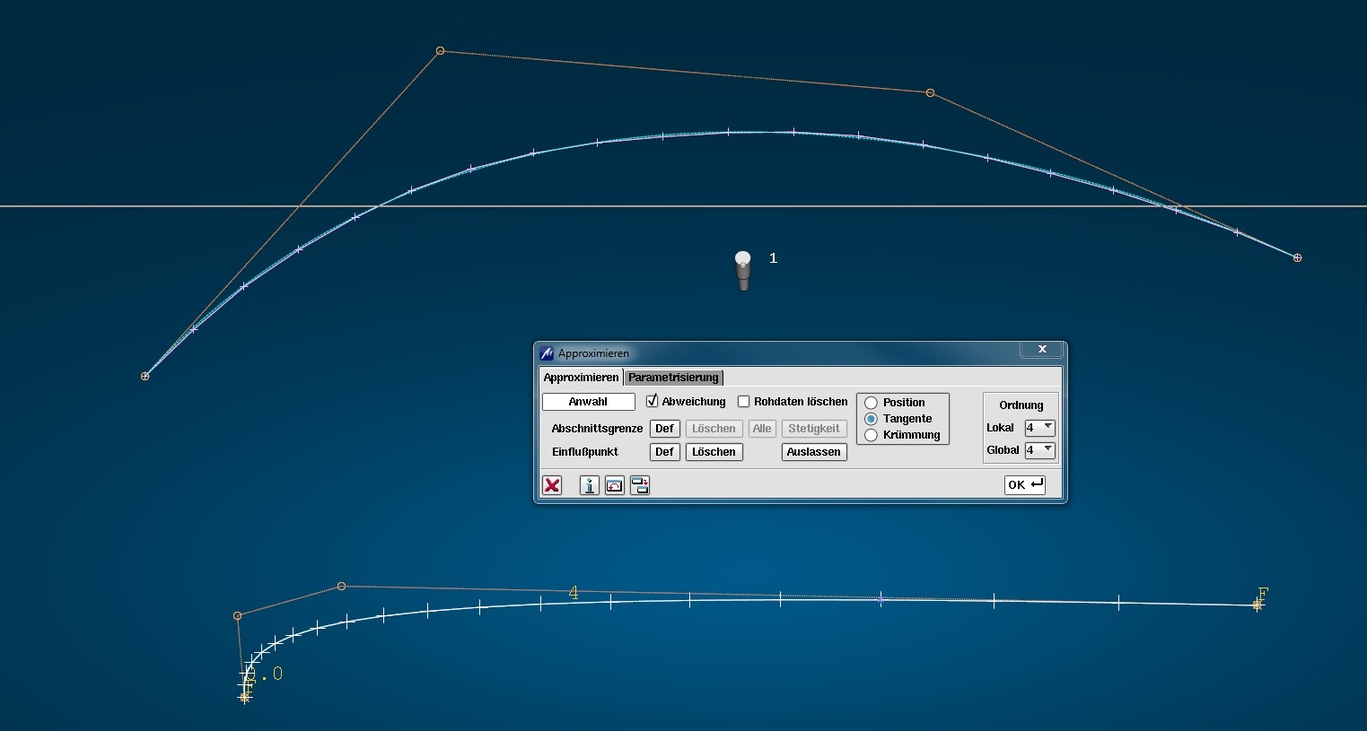
I was actually requesting that 2 years ago, McNeels answer to this was you need to interpolate or rebuild not approximate…
Although I don’t like to compare Surf with Rhino, it just shows what I mean by approximation, here are your curves reapproximated to the same parameters as chosen by you. As a proof that there is a functionality doable.
I frequently encounter students and young professionals in “isoparametric curve hell”, which makes G1, let alone G2 filleting and many other operations, like matching, fail or consume endless hours of work-time with a low quality result.
Best is always to work out a plausible patch-layout and then try using single-span Bezier/degree 5 or 7 curves.
Hi David - the Rebuild command samples the input curve at regular intervals to make its new curve - so areas where are is a of of change in curvature are always under represented, so to speak. You either need to use more points, or edit the result to locate more points in the areas where curvature is changing, to get close to the original.
oops, I guess that is not @davidcockey 's comment above…
How does the user change the number of points which Rebuild samples?
I added 75 knots to the curve with the problem in my example above. The curve was originally single span, degree 3 with 4 control points. The added knots resulted in a curve with exactly the same shape (e-12 difference) and also degree 3 but with 79 control points. Then I used Rebuild using 4 control points. The rebuilt curve is the same (e-09 difference) as the result of Rebuild with the original single span curve.
Preliminary conclusion - number of control points in the input curve to Rebuild does not affect the results if the shape of the input curve is the same. RebuildEx02.3dm (66.3 KB)